Body Electrical System
Button Engine Start System
In this manual: Body Electrical System
2steps
~12min
1/5difficulty
Done 0 of 2
Contents:
Description and Operation
Description
System Overview
The system offers the following features:- Switching between off, IG ON and power by pushing the start button.
- Controls external relays for ACC / IG1 / IG2 terminal switching and STARTER, without use of mechanical IG switch.
- Indicating the vehicle status on cluster by displaying messages.
- Immobilizer function by LF transponder communication between between fob and button start switch.
- Interface with Low Speed CAN vehicle communication network.
- Interface with LIN vehicle communication network depending on platform.
- Switching of ACC/IG1/IG2 terminal.
- Control of the STARTER relay based on communication with EMS ECU.
- Management of the Immobilizer function.
- Management of Button Start System warning function.
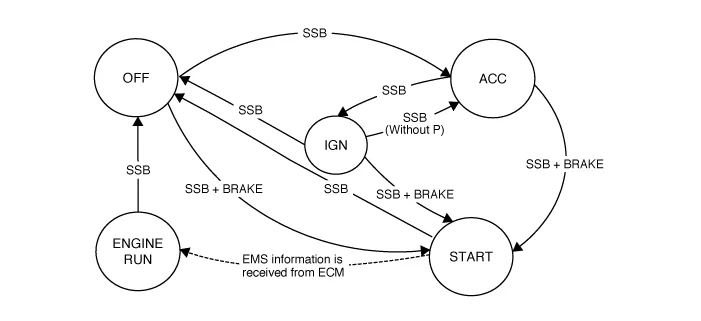

- Start/Stop Button (SSB) control
- Immobilizer communication (with ECM for releasing immobilizer)
- Authentication server (Validity of Transponder and in case of Smart Key option Passive FOB authentication)
- System consistency monitoring
- System diagnosis
- Control of display message / warning buzzer
- In case of no input signal for the brake switch (AT specification), the ACC mode shall cycle to “START” by pressing SSB for more than 10 seconds.
- In case of problems with communication between EMS and CAN (the EMS state), the “START” state cycles to the “ENGINE RUN” based on rpm input.
- In case that one out of two SSB input lines is disconnected, the electric power cycling is available when SSB is pressed twice within 10 seconds. The buzzer rings when the button is pressed for the first time. Electric power cycling is available and buzzer stops when the button is pressed twice within 10 seconds.

Start/stop button Terminal Function
Connector and Terminal Function
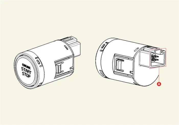
| Connector A | Terminal | Function | Terminal | Function |
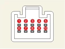 |
1 | SSB Switch 1 | 6 | Ground |
| 2 | - | 7 | SSB Switch 2 | |
| 3 | SSB Illumination ( + ) | 8 | Illumination ( - ) | |
| 4 | Immobilizer (Power) | 9 | - | |
| 5 | - | 10 | Immobilizer (Ground) |
Start/stop button Removal and Installation
Removal
- Remove the crash pad garnish [Passenger's side]. (Refer to Body - "Crash Pad Garnish")
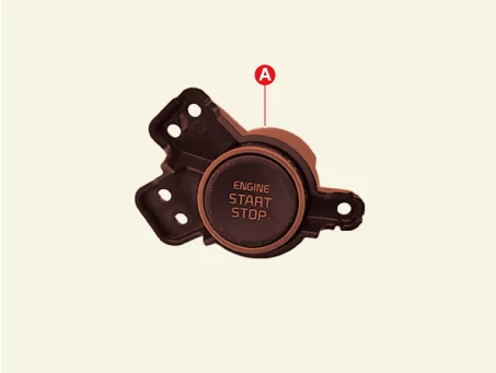
- Remove the Start / Stop Button (SSB) (A) after removing the screws.
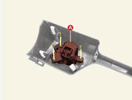
Installation
- Install in reverse order of removal.
Was this page helpful?