Body Electrical System
Charging System
In this manual: Body Electrical System
20steps
~120min
4/5difficulty
Done 0 of 20
Contents:
On Vehicle Inspection
On Vehicle Inspection
Diagnosis with KDS
- The body electrical system can be more quickly diagnosed for problems with the KDS (Refer to "DTC guide").
- Self diagnosis : Inspect the Diagnostic Trouble Code (DTC) with the KDS. (Refer to DTC guide when fault code is found.)
Refer to the KDS screen for operating conditions and details.
Wireless Power Charger (WPC) Description and Operation
Description
During IG ON, battery voltage is supplied to the wireless power charger system to transmit an output of 5 W to mobile phone. Schematic Diagram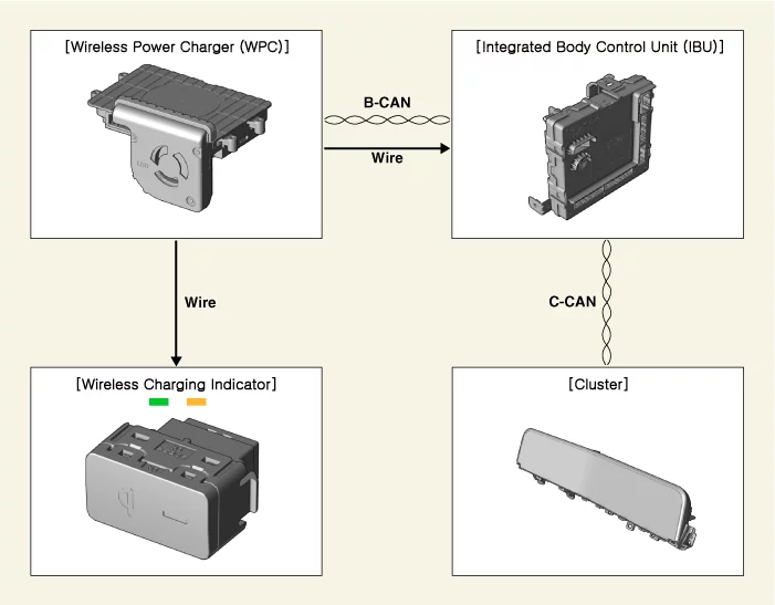
- Wireless power charger (WPC) : Negligence of mobile phone, foreign object detection (FOD) decision.
- Integrated body control unit (IBU) : Stops charging during the activation of Low Frequency (LF).
- Wireless charging indicator : Displays the charging status.
- Instrument cluster : Alerts about contact with mobile phone.
- Charging Function
- Activation method
a. Close all doors of the vehicle. b. Switch vehicle power to IG ON. c. Place the wireless charging-enabled mobile phone on the tray. - Charging status display
Mode Charging LED display Possible Cause Stand-by for charging LED turned OFF - Charging in process Amber LED turned ON - Charging completed Green LED turned ON - Charging error Amber LED blinks - FOD detection : Blinks 10 times and pause for 50 sec → FOD status re-check
- High Temp : Blinks 10 times when not charged by high temperature. LED OFF till the ERROR message is erased.
- Activation method
- Mobile phone neglect alert function
- Activation method
a. IG OFF when the phone is still charging. b. Check if there is a phone on wireless charging unit. c. Display warning message on the cluster if the phone is left in the WPC charge pad and the driver's door is opened or if the phone is left for more than 1 minute. (for about 4 ~ 5 seconds)

- Activation method
- Overheating prevention
- Activation method
a. If the thermistor temperature inside the wireless charging module rises above (158 °F (70 °C)), charging will stop to protect the mobile phone battery. - The amber LED of the charging display lamp blinks 10 times for 10 seconds.
b. After the thermistor temperature falls (LED remains OFF till the high temperature ERROR is erased), charging will re-start.
When the charging function is restarted, the amber LED of the charging display lamp will be turn on.
- Activation method
- Foreign matter detection
- Charging will be disabled if there are coins or other metallic objects between the wireless charging unit and the mobile phone. [Foreign matter]
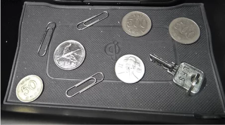
- Foreign matter : All metallic objects such as coins, clips and precious metals.
- The amber LED of the charging display lamp blinks 10 times for 10 seconds, and then it is turned off for 50 seconds (total 60 seconds).
- Do it twice (after 50 seconds off, check once and blink 10 times)
Be careful as touching the foreign matter by hand as it may cause burns.
- If a foreign substance is detected and the charging of the mobile phone is stopped, the charging resumes after about 60 seconds when the foreign substance is removed.
When the charging function is restarted, the amber LED of the charging display lamp will be turn on.
- Charging will be disabled if there are coins or other metallic objects between the wireless charging unit and the mobile phone. [Foreign matter]
- IBU unit low frequency (LF) interference prevention This function prevents interference between the wireless charging frequency and IBU frequency band.
- Wireless charging is stopped when the door is open or the IBU unit is in LF mode (searching for smart key). e.g. Wireless charging function is stopped if the driver carries the smart key out of the vehicle during IG ON.
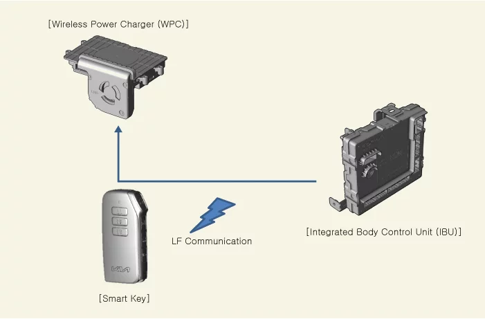
Charging will stop and the amber LED of the charging display lamp will turn off. - It will return to normal operating status when the LF mode of the IBU unit is completed.
- Wireless charging is stopped when the door is open or the IBU unit is in LF mode (searching for smart key). e.g. Wireless charging function is stopped if the driver carries the smart key out of the vehicle during IG ON.
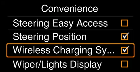
- Turn the wireless charging function ON/OFF with USM.
| Item | Condition | State |
| Protects against low/high voltage | Protects and stops charging under 8.5 V and over 16.5 V | LED OFF (Stops operation) |
| Charges between 9 - 16 volts | ||
| Protects against reverse voltage | Protects and stops charging in case of reverse voltage | LED OFF (Stops operation) |
| Protects against overcurrent | Protects and stops charging in case of detecting 4 amps | Amber LED blinks |
| Protects against overheating | Protects and stops charging in case of detecting 158 °F (70 °C) by internal temperature sensor of wireless charging module | Amber LED blinks |
| Resumes under 149 °F (65°C) | ||
| Foreign substances (Coins, clips, precious metals, etc.) |
Protects and stops charging in case of detecting foreign matter (overheating prevention) | Amber LED blinks |
| Prevents frequency interference | Protects and stops charging by activating IBU in case door or tailgate is open | LED OFF (Stops operation) |
| Resumes in 3.5 seconds after all doors and tailgate are closed and IBU operation is completed | ||
| Mobile phone neglect alert function | In case of smart phone on the charging pad when opening the door after IG OFF. | Displays warning message on the instrument panel (for about 4 - 5 seconds) |
Wireless Power Charger (WPC) Terminal Function
Connector and Terminal Function

| Connector A | Terminal | Function | Terminal | Function |
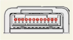 |
1 | Ground | 7 | - |
| 2 | Ground | 8 | L-CAN (Low) | |
| 3 | Wireless charging indicator (Amber) | 9 | L-CAN (High) | |
| 4 | Wireless charging indicator (Green) | 10 | - | |
| 5 | B-CAN (Low) | 11 | IG 1 | |
| 6 | B-CAN (High) | 12 | Battery ( + ) |
Wireless Power Charger (WPC) Removal and Installation
Removal
- Remove the console upper cover. (Refer to Body - "Console Upper Cover")
- Disconnect the wireless power charger connector (A), USB charger connector (B) and power outlet connector (C).
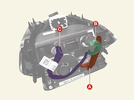
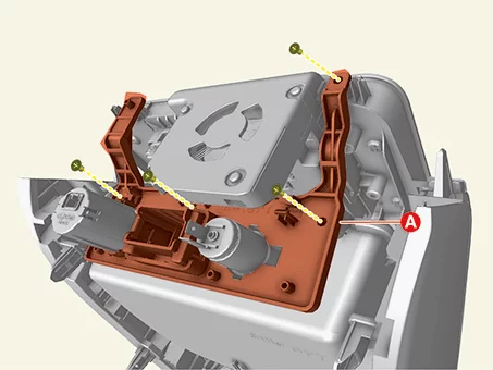
- Separate the USB charger bracket (A) after removing the screws.
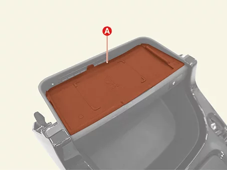
- Remove the wireless charging pad (A).
- Remove the wireless power charger (A) in the direction of the arrow after removing the screws.
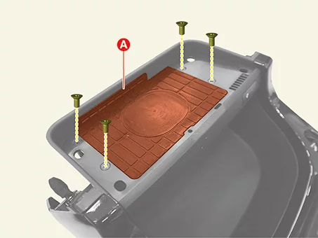

Installation
- Install in reverse order of removal.
Wireless Charging Indicator Terminal Function
Connector and Terminal Function
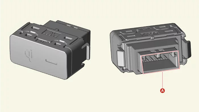
| Connector A | Terminal | Function |
 |
1 | Ground |
| 2 | Wireless charging indicator (Green) | |
| 3 | Wireless charging indicator (Amber) | |
| 4 | - | |
| 5 | Illumination ( - ) | |
| 6 | Illumination ( + ) |
Wireless Charging Indicator Removal and Installation
Removal
- Remove the console upper cover. (Refer to Body - "Console Upper Cover")
- Disconnect the wireless charging indicator connector (A).
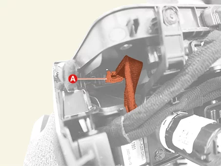
- Remove the wireless charging indicator (A) by pressing the hook in the direction of the arrow.

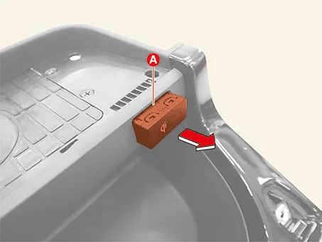
Installation
- Install in reverse order of removal.
USB Charger Terminal Function
Connector and Terminal Function
[Console Tray]

| Connector | Terminal | Function |
 |
1 | Ground |
| 2 | Illumination ( - ) | |
| 3 | Illumination ( + ) | |
| 4 | ACC |
[Rear Console Cover]
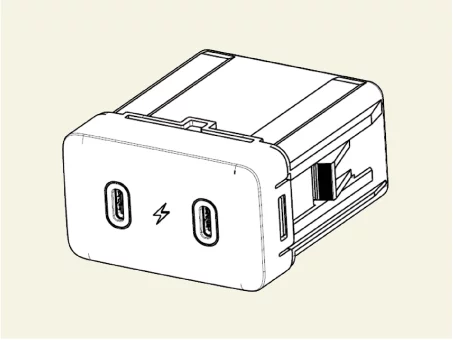
| Connector | Terminal | Function |
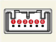 |
1 | Ground |
| 2 | Ground | |
| 3 | Illumination ( - ) | |
| 4 | Illumination ( + ) | |
| 5 | ACC | |
| 6 | ACC |
USB Charger Removal and Installation
Removal
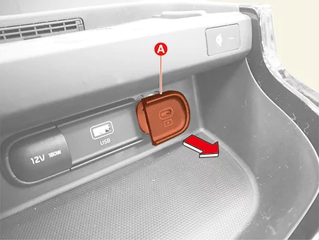
[Console Tray]- Remove the console upper cover. (Refer to Body - "Console Upper Cover")
- Disconnect the USB charger connector (A).
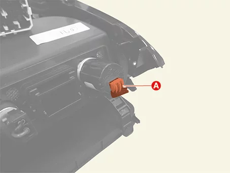
- Remove the USB charger (A) by pushing it in the direction of the arrow.
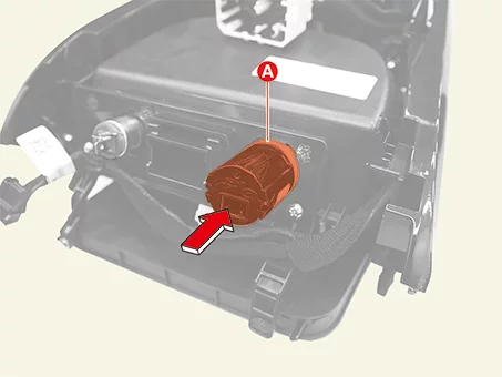
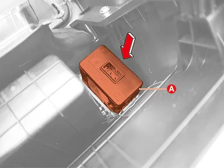
- Remove the floor console assembly. (Refer to Body - “Floor Console Assembly”)
- Disconnect the USB charger connector (A).

- Remove the U SB charger (A) by pushing it in the direction of the arrow.

Installation
- Install in reverse order of removal.
Was this page helpful?