Body Electrical System
Integrated Memory Seat (IMS)
In this manual: Body Electrical System
8steps
~48min
2/5difficulty
Done 0 of 8
Contents:
On Vehicle Inspection
On Vehicle Inspection
Diagnosis with KDS
- The body electrical system can be more quickly diagnosed for problems with the KDS (Refer to "DTC guide").
- Self diagnosis : Inspect the Diagnostic Trouble Code (DTC) with the KDS. (Refer to DTC guide when fault code is found.)
- S/W Management : Controlling other features including system option setting and zero point adjustment. (S/W Management → Power Seat Module → Seat Limit Position Setting)
Refer to the KDS screen for operating conditions and details.
Integrated Memory Seat (IMS) Unit Terminal Function
Connector and Terminal Function
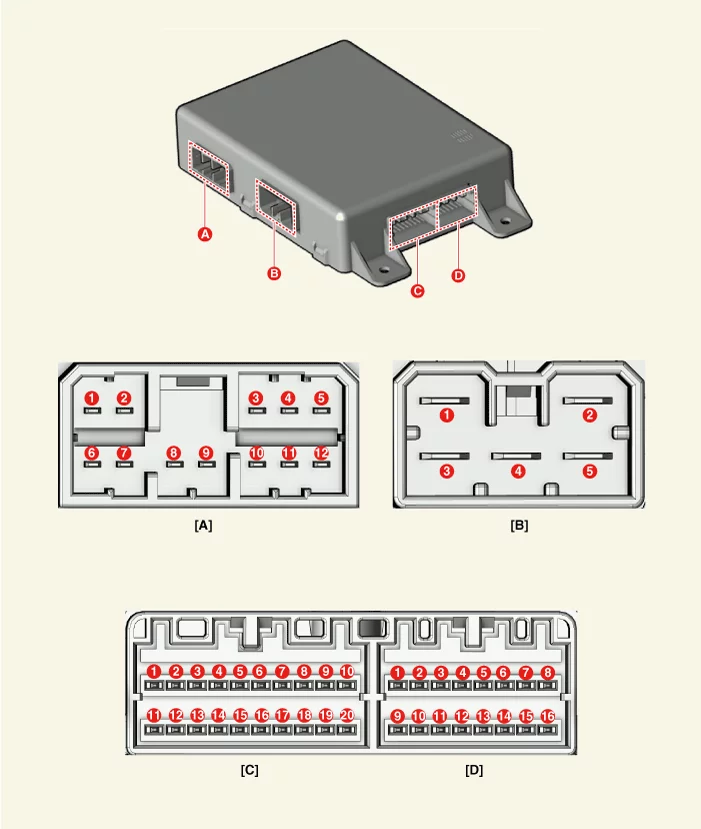
| Terminal | Function | |||
| Connector A | Connector B | Connector C | Connector D | |
| 1 | - | Battery (+) | Driver's slide switch (FWD) | - |
| 2 | Driver seat recline motor (FWD) | Ground | Driver seat recline switch (FWD) | Driver seat lumbar switch (FWD) |
| 3 | Driver seat height motor (Up) | Battery (+) | Driver seat tilt motor (up) | - |
| 4 | - | - | Driver seat height switch (Up) | B-CAN (High) |
| 5 | Driver seat slide motor (FWD) | Ground | - | B-CAN (Low) |
| 6 | - | - | - | |
| 7 | Driver seat recline motor (BWD) | - | IG 1 | |
| 8 | Driver seat tilt motor (Up) | Driver seat recline limit switch (FWD) | Battery (+) | |
| 9 | Driver seat tilt motor (Down) | Driver seat recline limit switch (BWD) | Ground | |
| 10 | Driver seat height motor (Down) | Sensor power | - | |
| 11 | - | Driver seat slide switch (BWD) | Driver seat lumbar switch (BWD) | |
| 12 | Driver seat slide motor (BWD) | Driver seat recline switch (BWD) | IMS Switch | |
| 13 | Driver seat tilt switch (Down) | - | ||
| 14 | Driver seat height switch (Down) | Ground | ||
| 15 | - | - | ||
| 16 | Driver seat slide motor (Sensor) | - | ||
| 17 | Driver seat recline motor (Sensor) | |||
| 18 | Driver seat tilt motor (Sensor) | |||
| 19 | Driver seat height motor (Sensor) | |||
| 20 | - | |||
Integrated Memory Seat (IMS) Unit Removal and Installation
Removal
- Remove the front seat assembly [Driver's seat]. (Refer to Body - "Front Seat Assembly")
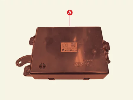
- Disconnect the memory Integrated Memory Seat (IMS) unit connectors (A).
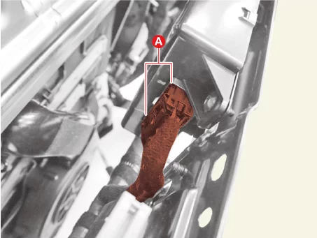
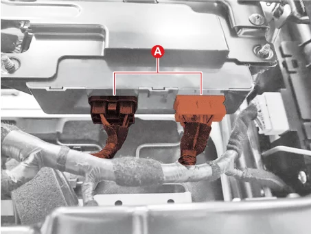
- Remove the memory Integrated Memory Seat (IMS) unit (A) after removing the screws.
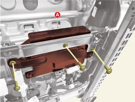
Installation
- Install in reverse order of removal.
Integrated Memory Seat (IMS) Switch Terminal Function
Terminal Function
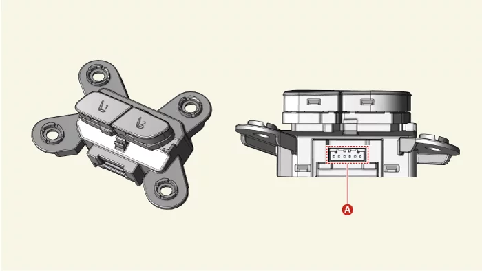
| Connector A | Terminal | Function |
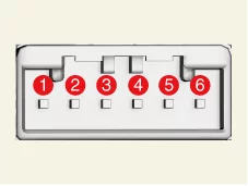 |
1 | Illumination ( + ) |
| 2 | - | |
| 3 | Driver's IMS switch | |
| 4 | - | |
| 5 | Ground | |
| 6 | Illumination ( - ) |
Integrated Memory Seat (IMS) Switch Removal and Installation
Removal
- Remove the front door trim [Driver's Side]. (Refer to Body - "Front Door Trim")
- Disconnect the memory power seat switch connector (A).
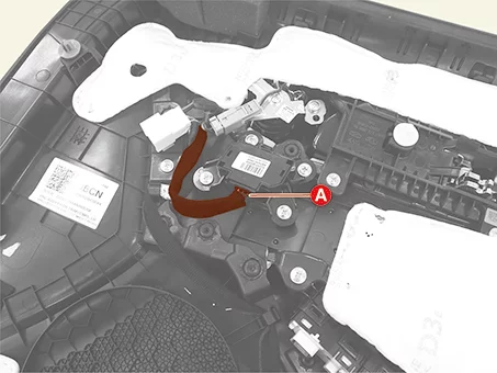
- Remove the memory power seat switch (A) after removing the screws.
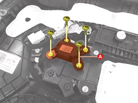
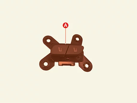
Installation
- Install in reverse order of removal.
Integrated Memory Seat (IMS) Switch Inspection
Inspection
- Remove the front door trim [Driver's Side]. (Refer to Body - "Front Door Trim")
- When each switch is pressed, check the continuity between integrated memory seat switch connector and ground.
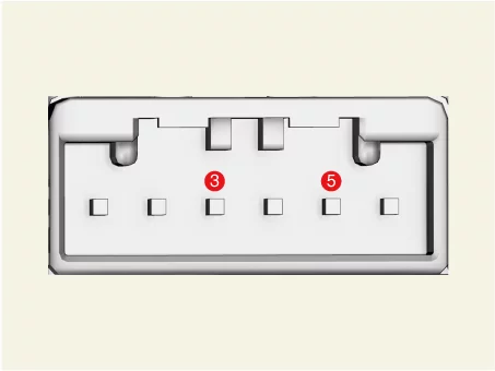
Switch Terminal Resistance (±1%) Memory 1 3 - 5 1,500 Ω Memory 2 3,300 Ω
Was this page helpful?