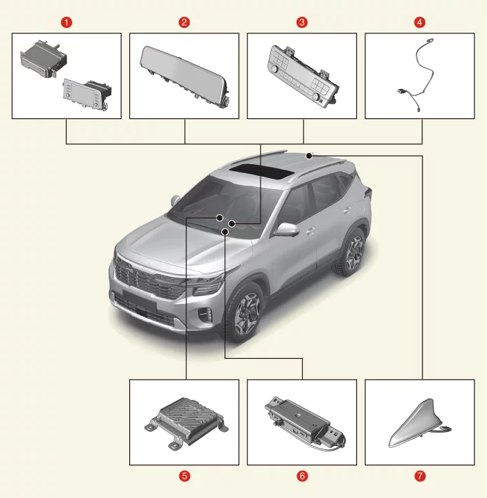
1. Audio/AVNT Head Unit 2. AVNT Monitor 3. AVNT Keyboad 4. Multimedia Jack
5. External Amplifier 6. Crash Pad Antenna 7. Roof Antenna
Description and Operation
Description
The Audio/AVNT system simplifies system manipulation and by unifying the vehicle information and user information displays, improves information search and operation experience. System Component
On Vehicle Inspection
On Vehicle Inspection
Diagnosis with KDS
The audio/AVNT system can be more quickly diagnosed for problems with the KDS (Refer to "DTC guide").
Self diagnosis : Inspect the Diagnostic Trouble Code (DTC) with the KDS. (Refer to DTC guide when fault code is found.)
S/W Management : Controlling other features including system option setting and zero point adjustment. (S/W Management → Audio Video Navigation → AVN/Audio Diagnostic Mode) (S/W Management → Amplifier → AMP Operation Test)
Refer to the KDS screen for operating conditions and details.
Audio/AVNT Head Unit Terminal Function
Connector and Terminal Function
[Display Audio Head Unit]
Terminal
Function
Connector A
Connector B
1
Left rear door speaker ( + )
-
2
Left rear door speaker ( - )
Mic ( + )
3
-
-
4
-
-
5
-
-
6
Rear view camera power
Illumination ( + )
7
Rear view camera video
M-CAN (High)
8
-
-
9
-
-
10
-
Battery (+)
11
USB (DTC)
Battery (+)
12
Steering wheel remote control switch
Ground
13
Left front door speaker ( + )
Ground
14
Left front door speaker ( - )
-
15
Right front door speaker ( - )
Mic ( - )
16
Right front door speaker ( + )
-
17
-
-
18
-
-
19
-
Illumination ( - )
20
Rear view camera power (Ground)
M-CAN (Low)
21
Rear view camera video (Ground)
-
22
-
ACC
23
-
-
24
-
-
25
-
-
26
Steering wheel remote control switch (ground)
-
27
Right rear door speaker ( - )
-
28
Right rear door speaker ( + )
-
29
-
-
30
-
-
31
-
-
32
-
-
33
Rear view camera shield (ground)
IG 1
34
-
-
35
-
-
36
-
37
-
38
Vehicle speed signal
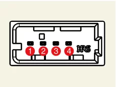
USB Connector
Terminal
Function
1
USB VCC
2
USB Data (Low)
3
USB Data (High)
4
USB Ground
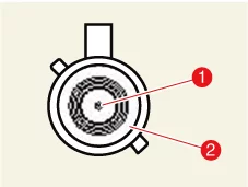
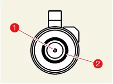
GPS Antenna connector
Terminal
Function
1
Signal
2
Ground
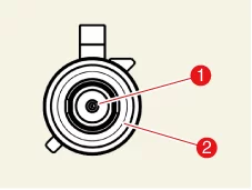
Radio Antenna connector
Terminal
Function
1
AM/FM
2
Ground
LTE Main antenna connector
Terminal
Function
1
Signal
2
Ground
[AVNT Head Unit]
Terminal
Function
Connector A
Connector A
Connector B
Connector C
Built-in amplifier
External amplifier
RVM Type
SVM Type
RVM Type
SVM Type
1
Left rear door speaker ( + )
-
Mic2 ( + )
-
2
Left rear door speaker ( - )
-
Mic1 ( + )
I-CAN (High)
3
-
Amplifier navigation voice ( - )
-
-
4
-
Amplifier SPDIF (High)
-
-
5
Reset
-
-
6
Rear view camera power
-
Rear view camera power
-
Illumination ( + )
-
7
Rear view camera video
-
Rear view camera video
-
M-CAN (High)
-
8
-
-
-
9
-
-
I-CAN (Low)
10
-
Battery (+)
-
11
USB (DTC)
Battery (+)
-
12
Steering wheel remote control switch
Mic1 (ground)
-
13
Left front door speaker ( + )
-
Mic2 (ground)
-
14
Left front door speaker ( - )
-
Mic2 ( - )
-
15
Right front door speaker ( - )
-
Mic1 ( - )
-
16
Right front door speaker ( + )
-
-
MTS Key pad
17
-
Amplifier navigation voice ( + )
-
-
18
-
Amplifier SPDIF (Low)
-
-
19
-
Amplifier SPDIF (ground)
Illumination ( - )
-
20
Rear view camera power (Ground)
-
Rear view camera power (Ground)
-
M-CAN (Low)
-
21
Rear view camera video (Ground)
-
Rear view camera video (Ground)
-
-
-
22
-
ACC
23
-
-
24
-
Monitor power
25
-
-
26
Steering wheel remote control switch (ground)
-
27
Right rear door speaker ( - )
-
-
28
Right rear door speaker ( + )
-
-
29
-
-
30
-
-
31
-
-
32
-
Ground
-
Ground
-
33
Rear view camera shield (ground)
-
Rear view camera shield (ground)
-
IGN (+ )
34
-
-
35
-
Monitor power (ground)
36
-
37
-
38
Vehicle speed signal
USB Connector
Terminal
Function
1
USB VCC
2
USB Data (Low)
3
USB Data (High)
4
USB Ground
GPS Antenna connector
Terminal
Function
1
Signal
2
Ground
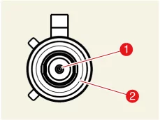
Radio antenna connector
Terminal
Function
1
Signal
2
Ground
LTE Sub antenna connector
Terminal
Function
1
Signal
2
Ground
LTE Main antenna connector
Terminal
Function
1
Signal
2
Ground
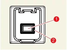
Monitor connector
Terminal
Function
1
Monitor
2
Ground
Audio/AVNT Head Unit Removal and Installation
Removal
[Display Audio Head Unit]
Remove the cluster [Standard Type]. (Refer to Instrument Cluster - "Cluster")
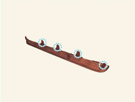
Remove the center fascia upper panel (A) by using the remover.
Clip position :
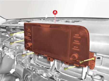
Remove the display audio head unit (A) after removing the screws.
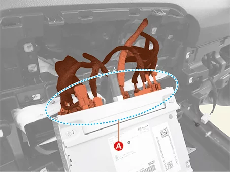
Disconnect the display audio head unit connectors (A).
Remove the cluster [Option Type]. (Refer to Instrument Cluster - "Cluster")
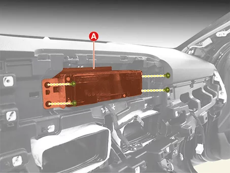
Remove the AVNT head unit after removing the screws.
Disconnect the AVNT head unit connectors (A).
[AVNT Head Unit]
Installation
Install in reverse order of removal.
AVNT Monitor Removal and Installation
Removal
[Option Type]
Remove the cluster [Option Type]. (Refer to Instrument Cluster - "Cluster")
Installation
Install in reverse order of removal.
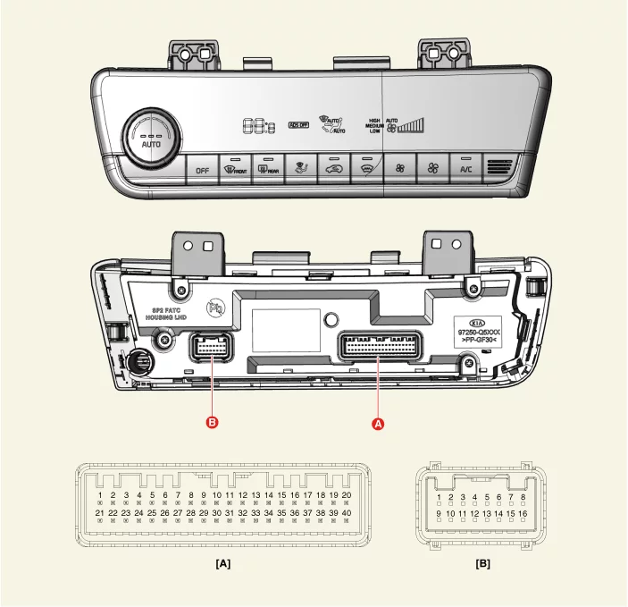
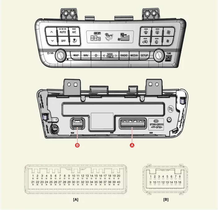
Audio/AVNT Keyboard Terminal Function
Terminal Function
[Display Audio Type]
Pin No
Connector A
Connector B
1
Battery ( + )
-
2
-
-
3
ILL ( + ) (TAIL)
-
4
Sensor ground REF (+5V)
Defogging actuator (Feedback)
5
Mode control actuator (Feedback)
Defogging actuator (Open)
6
Temperature actuator (Feedback)
Defogging actuator (Close)
7
Intake actuator (Feedback)
-
8
Evaporator temperature sensor (+)
Rear glass defogger indicator
9
Ambient temperature senor (+)
Rear glass defogger switch
10
Mode control actuator (Vent)
-
11
Mode control actuator (Def)
-
12
Temperature actuator (Cool)
Defog (TEMP)
13
Temperature actuator (Warm)
Defog (SCK)
14
Intake actuator (Fresh)
Defog (DATA)
15
Intake actuator (Recirculation)
-
16
HTD (Rear defog indicator)
Ground
17
Rear defogging switch
18
Blower relay
19
-
20
ILL ( + ) (RHEOSTAT)
21
IG2
22
IG 1
23
Blower motor (+)
24
Photo sensor (-)
25
-
26
-
27
-
28
-
29
-
30
AVNT head unit keyboard reset
31
Detent out ( - )
32
-
33
P-CAN (HIGH)
34
P-CAN (LOW)
35
FET (Drain Feedback)
36
FET (Gate)
37
ECV ( + )
38
ECV ( - )
39
Sensor ground (-)
40
Ground ( - )
[AVNT Specification]
Pin No
Connector A
Connector B
1
Battery ( + )
-
2
-
-
3
ILL ( + ) (TAIL)
-
4
Sensor ground REF (+5V)
Defogging actuator (Feedback)
5
Mode control actuator (Feedback)
Defogging actuator (Open)
6
Temperature actuator (Feedback)
Defogging actuator (Close)
7
Intake actuator (Feedback)
-
8
Evaporator temperature sensor (+)
Rear glass defogger indicator
9
Ambient temperature senor (+)
Rear glass defogger switch
10
Mode control actuator (Vent)
-
11
Mode control actuator (Def)
-
12
Temperature actuator (Cool)
Defog (TEMP)
13
Temperature actuator (Warm)
Defog (SCK)
14
Intake actuator (Fresh)
Defog (DATA)
15
Intake actuator (Recirculation)
-
16
HTD (Rear defog indicator)
Ground
17
Rear defogging switch
18
Blower relay
19
-
20
ILL ( + ) (RHEOSTAT)
21
IG2
22
IG 1
23
Blower motor (+)
24
Photo sensor (-)
25
-
26
-
27
-
28
-
29
-
30
AVNT head unit keyboard reset
31
Detent out ( - )
32
-
33
P-CAN (HIGH)
34
P-CAN (LOW)
35
FET (Drain Feedback)
36
FET (Gate)
37
ECV ( + )
38
ECV ( - )
39
Sensor ground (-)
40
Ground ( - )
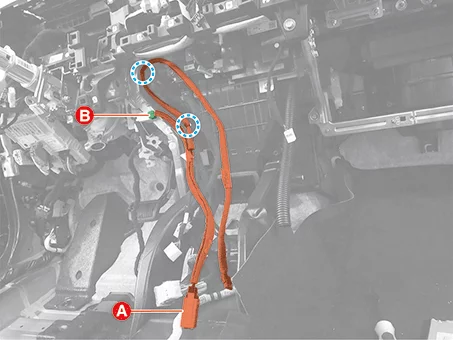
Audio/AVNT Keyboard Removal and Installation
Removal
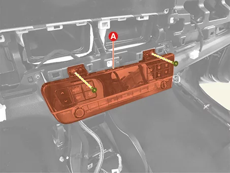
Remove the center air vent. (Refer to Body - "Crash Pad Air Vent")
Remove the Audio/AVNT keyboard (A) after removing the screws.
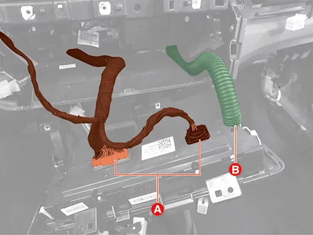
Disconnect the audio/AVNT keyboard connector (A) and the Heater & A/C control unit hose (B).
Installation
Install in reverse order of removal.
Speaker Removal and Installation
Removal
Front Center Speaker
Disconnect the negative ( - ) battery terminal.
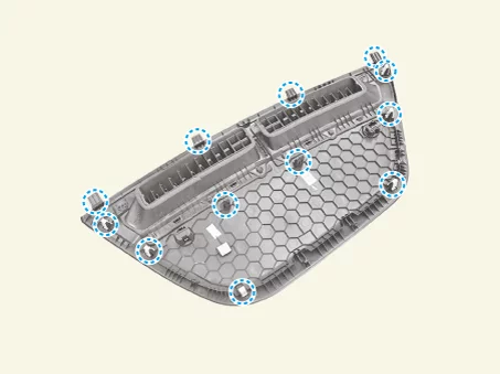
Remove the front center speaker grille.
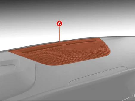
Remove the front center speaker grille (A) by using the remover.
Clip position :
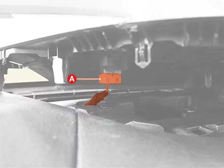
Disconnect the auto light sensor connector (A).
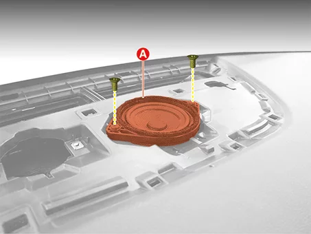
Remove the front center speaker (A) after removing the screws.
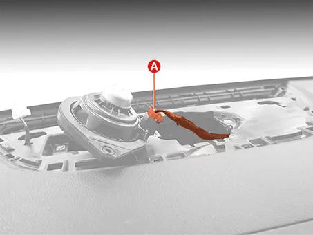
Disconnect the front center speaker connector (A).
Disconnect the negative ( - ) battery terminal.
Remove the front door trim. (Refer to Body - "Front Door Trim")
Disconnect the front tweeter speaker connector (A).
Remove the front tweeter speaker (A) after removing the screws.
Remove the front door trim. (Refer to Body - "Front Door Trim")
Disconnect the front door speaker connector (A).
Remove the front door speaker (A) after removing the bolts.
Remove the rear door trim. (Refer to Body - "Rear Door Trim")
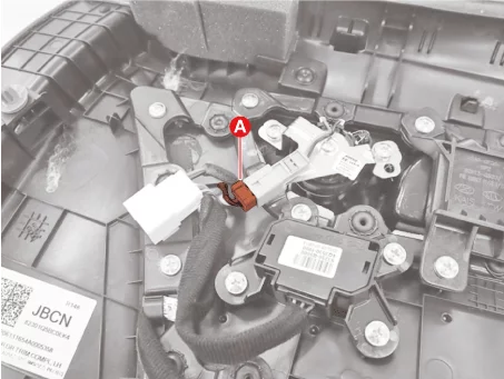
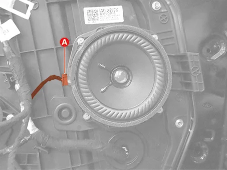
Disconnect the rear door speaker connector (A).
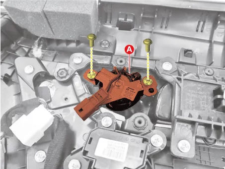
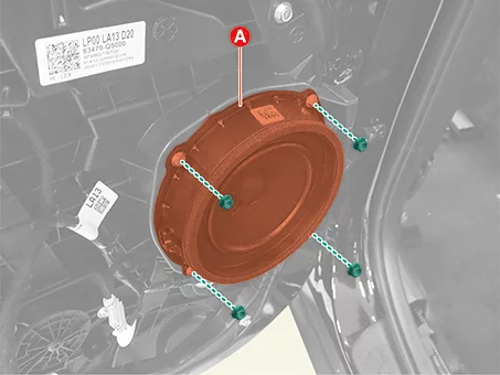
Remove the rear door speaker (A) after removing the bolts.
Disconnect the negative ( - ) battery terminal.
Remove the luggage side trim [RH]. (Refer to Body - "Luggage Side Trim")
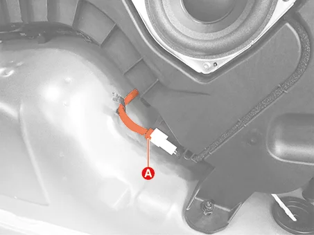
Disconnect the subwoofer speaker connector (A).
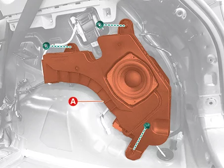
Remove the subwoofer speaker (A) after removing the nuts.
Front Tweeter Speaker Front Door Speaker Rear Door Speaker Subwoofer Speaker
Installation
Install in reverse order of removal.
Speaker Inspection
Inspection
Basic Inspection
Remove the screws to rule out the interference from the body trims and surrounding parts and then remove the speaker.
After removing the speaker, check the sound quality of the speaker with the connector plugged in.
Abnormal vibration
Make sure the mounting screws are properly tightened before replacing the speaker.
Reinstall the speaker and check that the symptom is resolved.
If the symptom does not disappear, replace the speaker with a new one.
Noise
Check that the speaker connector is properly connected and reinstall the connector if necessary.
If noises occur in radio mode, turn to the media player mode.
If noises occur in both modes, replace the speaker with a new one.
If noises occur only in the radio mode, the poor radio reception is the cause so do not replace the speaker.
Malfunctions
Check the plus (+) and negative (-) speaker terminals using an ohmmeter.
Individual Inspection
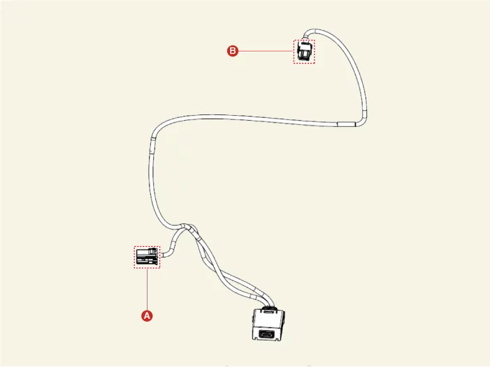
External AMP Terminal Function
Connector and Terminal Function
Terminal
Function
Connector A
Connector B
1
Battery (+)
Driver's tweeter speaker ( + )
2
Battery (+)
Passenger's tweeter speaker ( + )
3
Battery (+)
Subwoofer speaker ( + )
4
Battery (+)
-
5
-
-
6
MM-CAN (High)
-
7
MM-CAN (Low)
External amplifier navigation voice ( + )
8
ACC
-
9
-
-
10
-
-
11
-
-
12
-
Right rear door speaker ( + )
13
-
Left rear door speaker ( + )
14
-
Front center speaker ( + )
15
-
-
16
Ground
Driver's tweeter speaker ( - )
17
Ground
Passenger's tweeter speaker ( - )
18
Ground
Subwoofer speaker ( - )
19
Ground
-
20
External amplifier SPDIF (high)
-
21
External amplifier SPDIF (low)
External amplifier navigation voice ( - )
22
External amplifier SPDIF (ground)
-
23
-
-
24
IG 1
-
25
-
Right rear door speaker ( - )
26
-
Left rear door speaker ( - )
27
-
Front center speaker ( - )
28
-
-
External AMP Removal and Installation
Removal
Remove the front seat assembly [Passenger's seat]. (Refer to Body - "Front Seat Assembly")
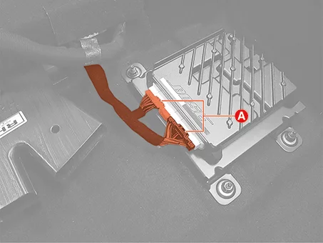
Disconnect the external amplifier connectors (A).
Remove the external amplifier (A) after removing the mounting nuts.
Installation
Install in reverse order of removal.
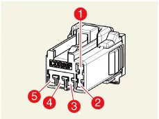
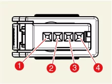
Multimedia Jack Terminal Function
Connector and Terminal Function
Connector A
Terminal
Function
1
DTC
2
-
3
Illumination ( + )
4
Illumination ( - )
5
Ground
Connector B
Terminal
Function
1
USB Ground
2
USB Data (High)
3
USB Data (Low)
4
USB vcc
Multimedia Jack Removal and Installation
Removal
Remove the main crash pad assembly. (Refer to Body - "Main Crash Pad Assembly")
Remove the multimedia jack.
Disconnect the multimedia jack connector (B).
Remove the multimedia jack (A).
Clip position :
Installation
Install in reverse order of removal.
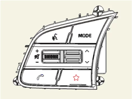
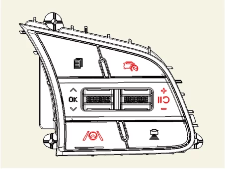
Steering Wheel Remote Controller (SWRC) Terminal Function
Connector and Terminal Function
[Audio + Bluetooth + Voice]
Connector
Terminal
Function
1
Audio switch ( + )
2
-
3
Illumination ( + )
4
-
5
Illumination ( - )
6
Audio switch ( + )
[Trip + SCC + LFA]
Connector
Terminal
Function
1
Trip switch 1 ( + )
2
Trip switch 2 ( + )
3
Illumination ( + )
4
-
5
Illumination ( - )
6
Trip switch ( - )
Steering Wheel Remote Controller (SWRC) Removal and Installation
Removal
Remove the steering wheel. (Refer to Steering System - "Steering Wheel")
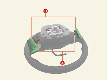
Remove the paddle shifter switches.
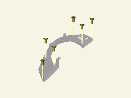
Remove the paddle shifter switch screws (A).
Separate the paddle shifter switches (A) by using a remover.
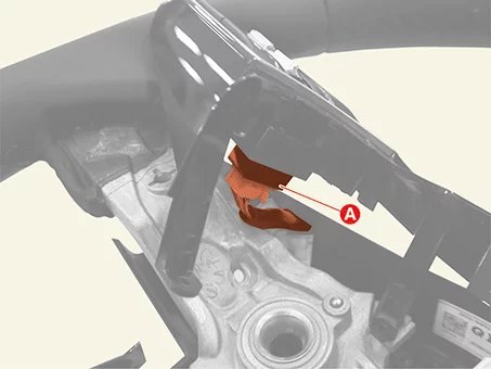
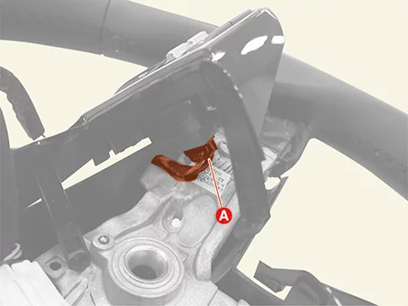
Remove the paddle shifter switches (B) by disconnecting the connectors (A).
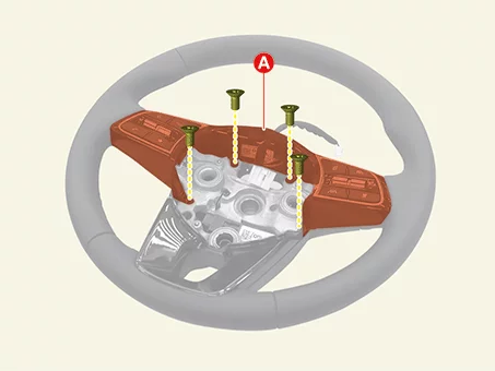
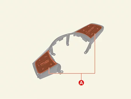
Remove the Steering Wheel Remote Control (SWRC) switch and bezel (A).
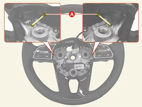
Disconnect the SWRC switch connectors (A).
Remove the SWRC (A) after removing the screws.
Installation
Install in reverse order of removal.
Antenna Removal and Installation
Removal
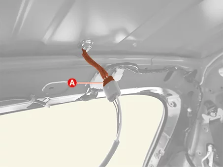
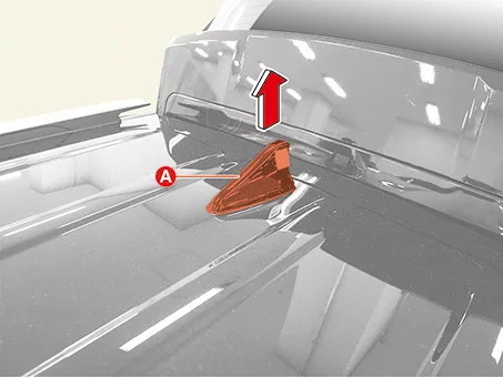
Roof Antenna
Remove the roof trim assembly. (Refer to Body - "Roof Trim Assembly")
Remove the roof antenna.
Disconnect the roof antenna connector (A).
Remove the roof antenna nut (A).
Tightening torque : 7.8 - 11,8 N·m
Remove the roof antenna (A).
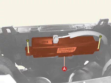
Remove the audio/AVNT head unit (Refer to Audio/AVNT System - "Audio/AVNT Head Unit")
Remove the crash pad antenna (A) after removing the screws.
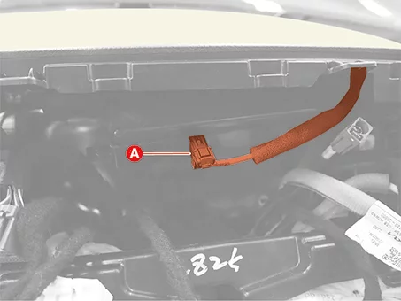
Disconnect the crash pad antenna connector (A).
Crash Pad Antenna
Installation
Install in reverse order of removal.
Mic Removal and Installation
Removal
Remove the overhead console lamp. (Refer to Lighting System - "Overhead Console Lamp")
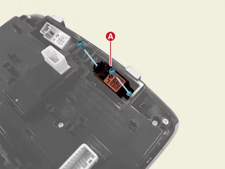
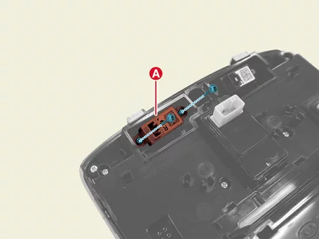
Remove the handsfree mic (A) after removing the screws. [LH] [RH]
Installation
Install in reverse order of removal.
Mic Inspection
Inspection
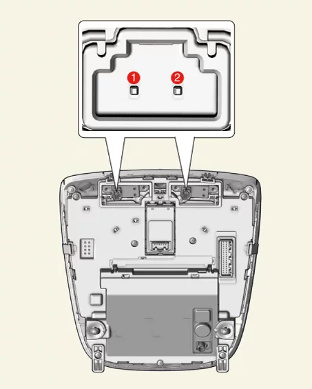
Remove the overhead console lamp. (Refer to Lighting System - "Overhead Console Lamp")