- The distance over which Radio Frequency (RF) Receiver can receive a FOB transmission signal : 30 m (98.4 ft.) - The distance over which Low Frequency (LF) antenna(Outer Handle/ Tailgate ) can detect FOB : 0.7 m (2.29 ft.)
Battery life
More than 2 years (20 times / a day)
An inappropriately disposed battery can be harmful to the environment and human health.
The smart key system can be more quickly diagnosed for problems with the KDS (Refer to "DTC guide").
Self diagnosis : Inspect the Diagnostic Trouble Code (DTC) with the KDS. (Refer to DTC guide when fault code is found.)
S/W Management : Controlling other features including system option setting and zero point adjustment. (S/W Management → Integrated Body Control Unit-SMK → Smart Key Code Saving) (S/W Management → Integrated Body Control Unit-SMK → Antenna Status Check) (S/W Management → Integrated Body Control Unit-SMK → FOB KEY STATUS INFORMATION) (S/W Management → Integrated Body Control Unit-SMK → SMK STATUS INFORMATION) (S/W Management → Integrated Body Control Unit-SMK → Neutralization Mode)
Refer to the KDS screen for operating conditions and details.
Code Saving
Code Saving
Refer to the KDS screen for operating conditions and details.
Smart Key Code Saving
Perform the order below with the KDS when registering the smart key. (S/W Management → IBU-SMK → Smart Key Code Saving)
Perform the order below with the KDS when checking the operation of the smart key. (S/W Management → IBU-SMK → SMK STATUS INFORMATION)
Smart Key Status Check
Smart Key Unit Removal and Installation
Removal
Integrated Body Control Unit (IBU)
Remove the Integrated Body Control Unit (IBU). (Refer to Body Electrical System - "Integrated Body Control Unit (IBU)")
Remove the door outside handle. (Refer to Front Door - "Front Door Handle")
Remove the tailgate outside handle assembly. (Refer to Body - "Tailgate Outside Handle")
Remove the front bumper assembly. (Refer to Body - "Front Bumper Assembly")
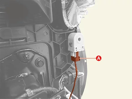
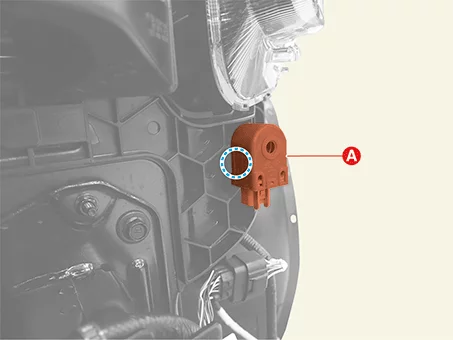
Disconnect the buzzer connector (A).
Remove the buzzer (A).
Clip position :
Front Door Outside Handle Tailgate Outside Handle Buzzer
Installation
Install in reverse order of removal.
Smart Key Unit Inspection
Inspection
Integrated Body Control Unit (IBU)
Inspect the IBU with the KDS. (Refer to Smart Key System - "On Vehicle Inspection")
Remove the door outside handle. (Refer to Body - "Front Door Outside Handle")
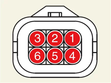
Disconnect the front door outside handle connector and then check for continuity between terminals No 1 and No 6.
Terminal
Function
SMK
NFC
1
Battery (+)
Battery (+)
2
-
L-CAN (Low)
3
Driver's door lock/unlock switch
Driver's door lock switch
4
Driver's door antenna (ground)
Driver's door unlock switch
5
-
L-CAN (High)
6
Ground
Ground
Remove the tailgate lid lower trim. (Refer to Body - " Tailgate Lid Trim")
Check for continuity between the terminals. [Type A]
Terminal
Function
Switch OFF
Switch ON
3 - 4
No continuity
Continuity
[Type B]
Terminal
Function
Switch OFF
Switch ON
3 - 4
No continuity
Continuity
Front Door Outside Handle Tailgate Outside Handle Switch
Smart Key Antenna Removal and Installation
Removal
Interior Antenna 1
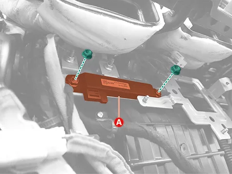
Remove the floor console assembly. (Refer to Body - “Floor Console Assembly”)
Disconnect the interior antenna 1 connector (A).
Remove the interior antenna 1 (A) after removing the nuts.
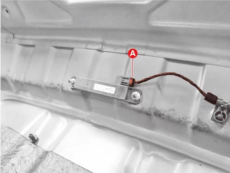
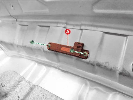
Disconnect the negative ( - ) battery terminal.
Remove the rear transverse trim. (Refer to Body - "Rear Transverse Trim")
Disconnect the interior antenna 3 connector (A).
Remove the interior antenna 3 (A) after removing the nuts.
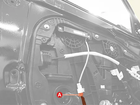
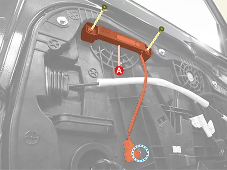
Remove the front door trim. (Refer to Body - "Front Door Trim")
Disconnect the front door antenna connector (A).
Remove the front door antenna (A) after removing the screws.
Clip position :
Remove the front door outside handle. (Refer to Body - "Front Door Outside Handle")
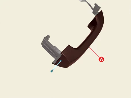
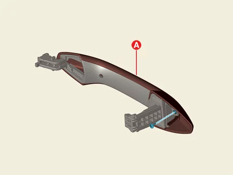
Remove the handle cover (A) after removing the screw. Driver's Side Passenger's Side
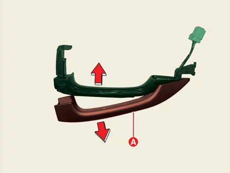
Remove the handle cover (A) by pulling it in the direction of the arrow.
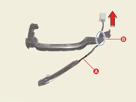
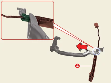
Remove the antenna.
Move the antenna wiring (A) to (B) by pulling it in the direction of the arrow.
Remove the antenna (A) by pulling it in the direction of the arrow.
Disconnect the negative ( - ) battery terminal.
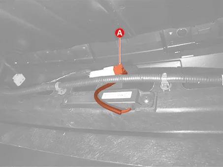
Remove the rear bumper antenna connector (A).
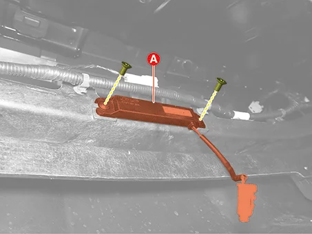
Remove the rear bumper antenna (A) after removing the screws.
Interior Antenna 3 Front Door Antenna #1 Front Door Antenna #2 Rear Bumper Antenna
Installation
Install in reverse order of removal.
Install in reverse order of removal.
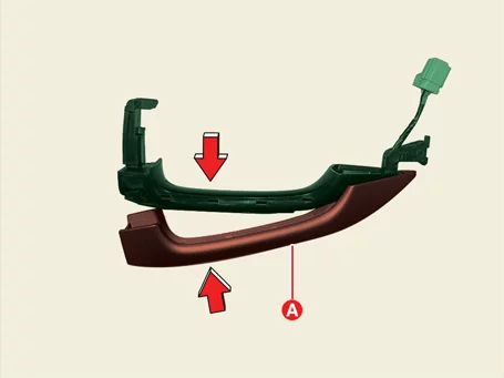
Install the handle cover as the procedures below.
Fix the handle's (A) area to handle cover's (B) area.
Install the handle cover (A) by pushing it in the derection of the arrow.