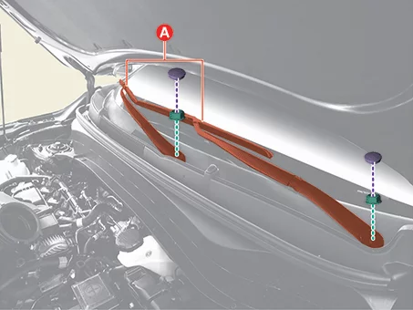
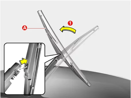
Remove the wiper arms (A) by removing the nuts after removing the caps.
Tightening torque : 22.6 - 26 N·m
Rear Wiper Arm
Separate the rear wiper arm cap (A) by pulling in the direction of the arrow.
Remove the rear wiper arm (A) after removing the nut. Tightening torque : 3.9 - 5,9 N·m (0.4 - 0.6 kgf·m, 2.9 - 4.3 lb·ft, 34.7 - 52.1 lb·in)
Installation
Install in reverse order of removal.
When installing, place the wiper arm to the specified position and then tighten the nut.
[Front Wiper]
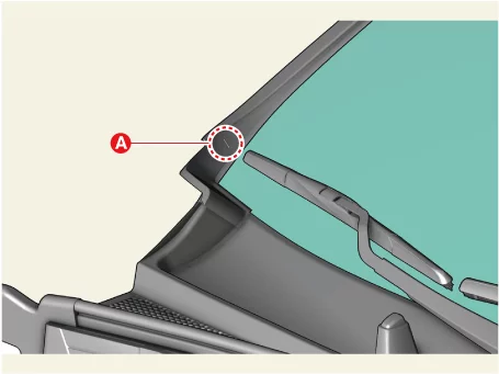
Place the wipers to the marking (A) position of cowl top cover.
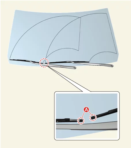
Place the wipers to the marking (A) position of windshield glass.
Wiper Motor Terminal Function
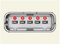
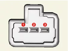
Connector and Terminal Function
[Front Wiper Motor]
Connector A
Terminal
Function
1
Front wiper (High)
2
Front wiper (Low)
3
Battery (+)
4
Front wiper (Parking)
5
Ground
[Rear Wiper Motor]
Connector A
Terminal
Function
1
Rear wiper (Low)
2
Ground
3
Rear wiper (Parking)
Wiper Motor Removal and Installation
Removal
Front Wiper Motor
Disconnect the negative ( - ) battery terminal.
Remove the cowl top cover. (Refer to Body - "Cowl Top Cover")
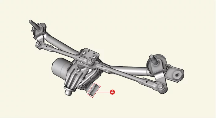
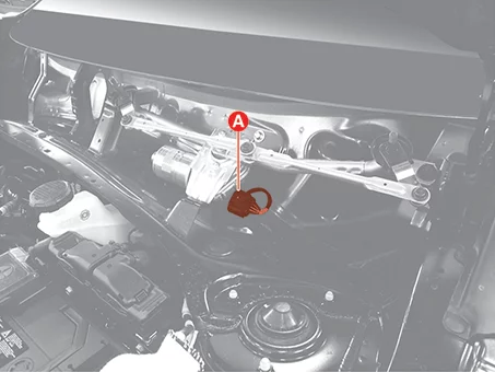
Disconnect the wiper motor connector (A).
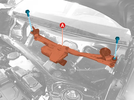
Remove the wiper motor (A) after removing the bolts.
Tightening torque : 6.9 - 10,8 N·m
Rear Wiper Motor
Remove the rear wiper arm. (Refer to Wiper/Washer - "Wiper Arm")
Remove the tailgate lid lower trim. (Refer to Body - "Tailgate Lid Trim")
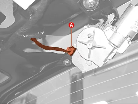
Disconnect the rear wiper motor connector (A).
Remove the rear wiper motor (A) after removing the bolts.
Tightening torque : 6.9 - 10,8 N·m
Installation
Install in reverse order of removal.
Washer Motor Removal and Installation
Removal
Washer Motor
Disconnect the negative ( - ) battery terminal.
Remove the engine room under cover. (Refer to Engine Mechanical System - "Engine Room Under Cover")
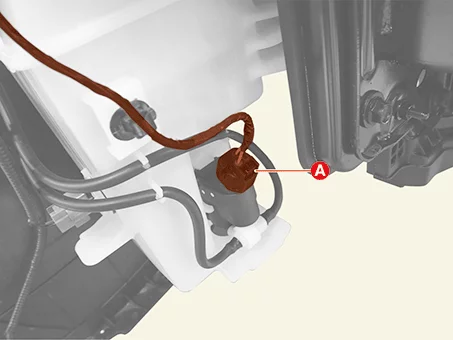
Disconnect the washer motor connector (A).
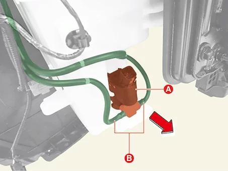
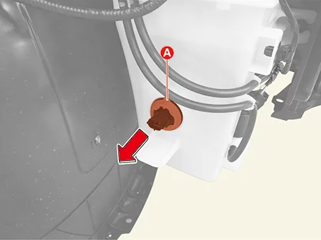
Remove the washer motor (A) in the direction of the arrow after separating the washer nozzle hoses (B).
Washer fluid is drained when removing washer motor.
Disconnect the negative ( - ) battery terminal.
Remove the engine room under cover. (Refer to Engine Mechanical System - "Engine Room Under Cover")
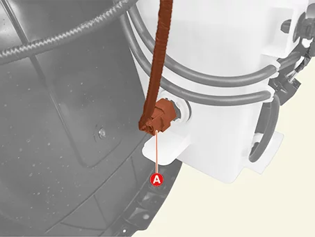
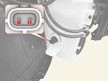
Disconnect the washer fluid level sensor connector (A).
Remove the washer level sensor (A) in the direction of the arrow.
Remove the engine room under cover. (Refer to Engine Mechanical System - "Engine Room Under Cover")
Remove the front wheel guard [Passenger's side]. (Refer to Body - "Front Wheel Guard")
Disconnect the washer motor connector (A).
Disconnect the washer fluid level sensor connector (A).
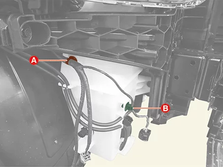
Remove the wiring clips (A), (B).
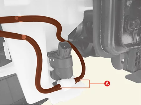
Separate the washer nozzle hoses (A).
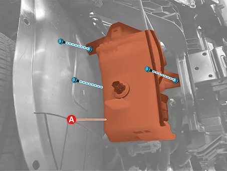
Remove the reservoir tank (A) after removing the bolts.
Tightening torque : 6.9 - 10,8 N·m
Washer Fluid Level Sensor Reservoir tank
Installation
Install in reverse order of removal.
Washer Motor Inspection
Inspection
Washer Motor
Before filling the reservoir tank with water, check the filter for foreign material or contamination. → Clean the filter if necessary
Using low-grade washer fluid may clog the washer pump and cause the malfunction of the pump motor.
Fill the washer fluid after installing the washer motor in the reservoir tank.
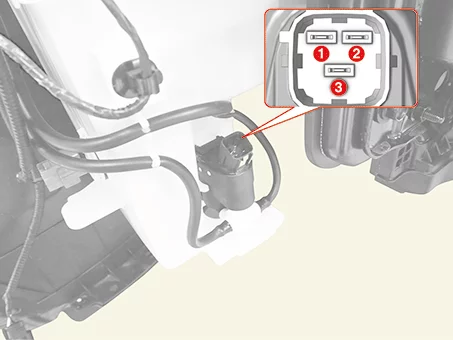
Connect terminal 1 to the battery ( - ) terminal and sequentially connect terminals 2 and 3 to the battery ( + ) terminal.
Check the washer motor operates normally and water sprays from the washer nozzles.
If they are abnormal, replace the washer motor.
Terminal
Function
1
Ground
2
Washer ( + )
3
Rear Washer ( + )
Disconnect the negative ( - ) battery terminal.
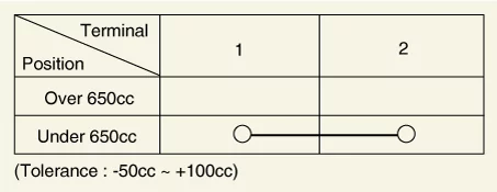
Drain the washer fluid less than 650 cc.
Check the continuity of between terminals.
Washer Fluid Level Sensor
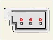
Rain Sensor Terminal Function
Connector and Terminal Function
Connector A
Terminal
Function
1
Battery (+)
2
Ground
3
LIN
Rain Sensor Removal
Removal
Do not damage or touch the silicone.
Be careful so that the silicon is not contaminated by foreign substances, dust, etc.
Use caution, as the silicon may be damaged if you try to separate the rain sensor using force.
The dust or foreign substance on the rain sensor may have bad influence on the performance of the rain sensor. In order to ensure accurate function of the rain sensor, protect the sensor surface with the protection cover until the sensor is installed on the bracket.
The coupling pad on the rain sensor surface is adhesive and the coupling pad may stick to the windshield during the use depending on the environment condition. Therefore, it may be damaged when you try to remove the rain sensor from the windshield if using force. Use caution when separating it from the windshield.
Disconnect the negative ( - ) battery terminal.
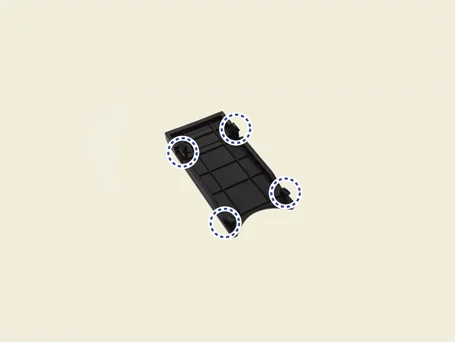
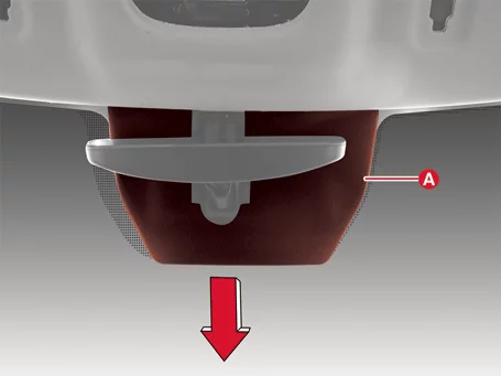
Remove the multi sensor blanking cover (A).
Clip position :
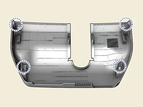
Remove the multi sensor cover (A) in the direction of the arrow.
Clip position :
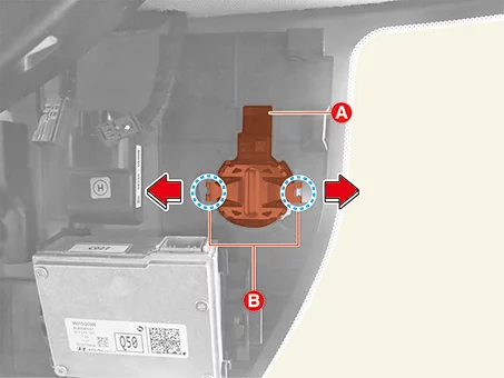
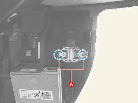
Disconnect the rain sensor connector (A).
Remove the rain sensor.
Separate both clips (B) of the rain sensor in the direction of the arrows by using the flat-blade screwdriver.
Remove the rain sensor (A) from the windshield glass.
Sensor may be damaged when you try to remove the rain sensor from the windshield using force. Use caution when separating it from the windshield.
When detaching the silicone under a high temperature, it may be easily damaged because of the adhesive strength of the silicone. Remove the silicone in a cool environment.
Silicone Pad Reuse Criteria After Rain Sensor Removal and Installation Precautions (Play ▶)
Video: Silicone Pad Reuse Criteria After Rain Sensor Removal and Installation Precautions
Notes When Refering Video This video provides guidance for understanding complex or hard-to-follow procedures by showing each step clearly. As needed, the video also provides clear guidance on essential procedural steps, including adjustment and diagnostic processes, the use of SSTs, and precautions to avoid component damage.
This video is created using common specifications and may differ from the actual vehicle.
The location and repair procedures of the parts may vary depending on vehicle model, model year, region, and specifications.
Check the KDS guide for detailed information on how to use the KDS.
Check the manual for detailed maintenance procedures.
Unauthorized reproduction, distribution, or sharing of this video is prohibited.
Rain Sensor Installation
Installation
Install in reverse order of removal.
When installing the rain sensor, do not fix it by pressing both spring arms (A) at the same time.
An incorrectly mounted snap connection may cause malfunctions of the rain/light sensor.
Check the operation of the rain sensor and the light sensor before mounting.
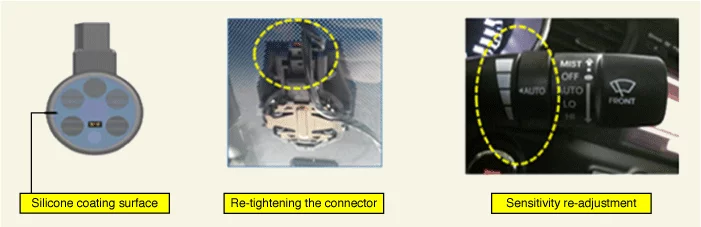
Check the sensor for silicon damage.
Check whether the rain sensor connector is tightened.
Check whether the rain sensor and bracket are properly tightened.
Check whether the sensor mounted area is free from foreign matters.
Recalibrate sensitivity of the switch if the auto-wiping operation is having too little or too much sensitivity.
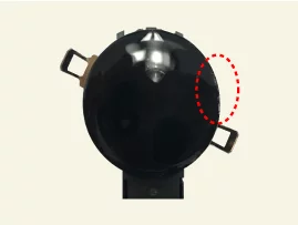
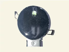
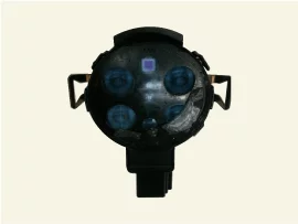
In case the silicone of the rain sensor is normal or slightly damaged as shown in the images below, it can be reused.
Normal
Damage within 1.5 mm of outer part
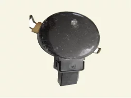
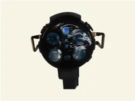
In case the silicone of the rain sensor is damaged as shown in the below images, it should be replaced with a new silicone.
Damage
Fingerprint
Damage
Damage
If the rain sensor silicone is damaged, replace it as follows.
Remove the damaged silicone gel pad from the lens plate completely.
Be careful not to damage or contaminate the surface of the lens plate during removal.
Attach the new silicone gel pad after removing the silicone paper then remove the transparent film.
When attaching the silicone gel pad to the sensor, be careful not to contaminate.
It is very important that the silicon (coupling pad) is completely pushed against the windshield and stuck without any air bubble.
In case of replacing the damaged windshield, you may reuse the undamaged existing rain sensor.
The windshield glass has to be clean and free of contamination or foreign substances.
Wiper Blade Replacement
Replacement
Front Wiper Blade
After turning off the engine, move the wiper switch to the single wiping (MIST) position within 20 seconds and hold the switch more than 2 seconds until the wiper blade is in the service position.
After IG ON, move the wiper switch to the single wiping (MIST) and wiper arms will return to the normal operating position.
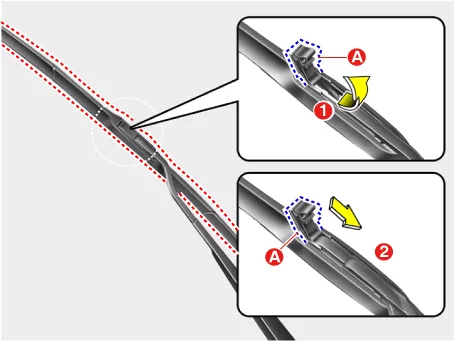
Remove the blade by pushing it in the direction of the arrow after opening the hook (A).
Install in reverse order of removal.
Remove the blade (A) by pulling it in the direction arrow after opening the hook.