The lighting system can be more quickly diagnosed for problems with the KDS (Refer to "DTC guide").
Self diagnosis : Inspect the Diagnostic Trouble Code (DTC) with the KDS. (Refer to DTC guide when fault code is found.)
Back-up Lamp Removal and Installation
Removal
Remove the rear bumper assembly. (Refer to Body - "Rear Bumper Assembly")
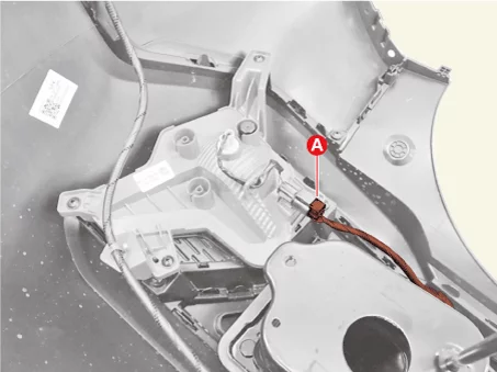
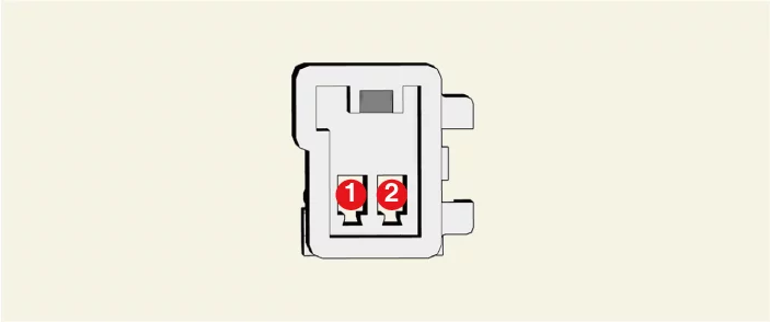
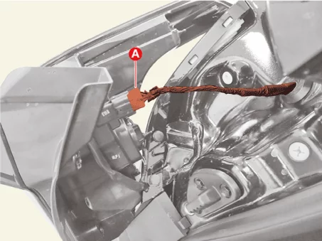
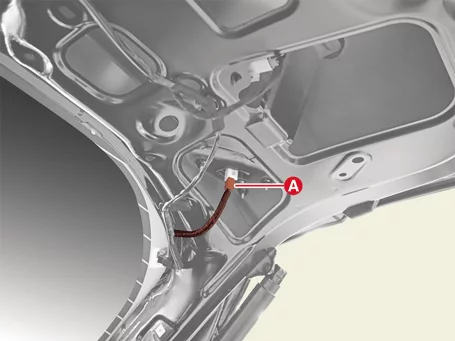
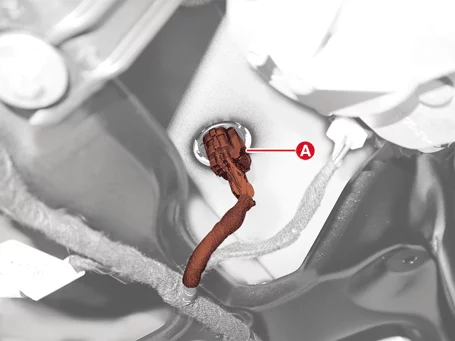
Disconnect the back-up lamp connectors (A).
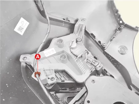
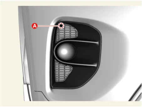
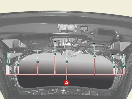
Remove the wiring clip (A) by using the remover.
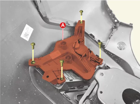
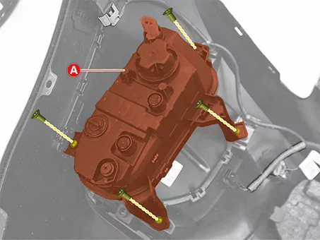
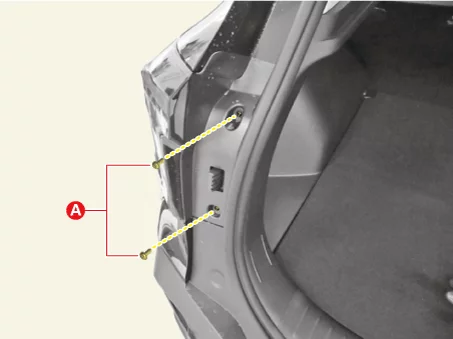
Remove the back-up lamp (A) after removing the screws.
Installation
Install in reverse order of removal.
Back-up Lamp Replacement
Replacement
Bulb
[Back-up Lamp]
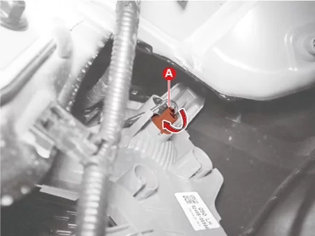
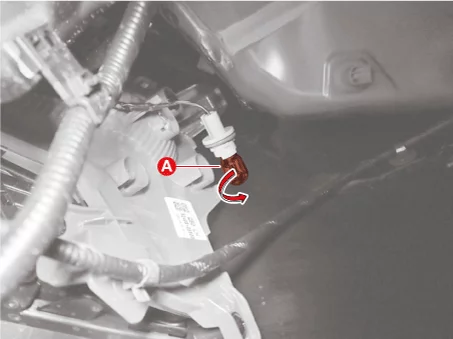
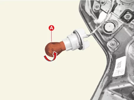
Remove the back-up lamp bulb socket (A) by turning in the counterclockwise.
Replace the back-up lamp bulb (A).
Install in reverse order of removal.
Fog Lamp Removal and Installation
Removal
Front Fog Lamp
Remove the front bumper. (Refer to Body - "Front Bumper Assembly")
Remove the front fog lamp assembly (A) after removing the screws.
Installation
Install in reverse order of removal.
Fog Lamp Replacement
Replacement
Absorbent
Remove the front bumper. (Refer to Body - "Front Bumper Assembly")
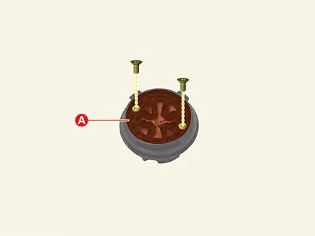
Remove the dust cap (A) by turning in the counterclockwise direction.
Remove the absorbent bracket (A) after removing the screws.
Replace the absorbent (A).
Fold the new absorbent material as the picture below.
Install in reverse order of removal.
Fog Lamp Adjustment
Adjustment
Fog Lamp Aiming Turn the adjusting gear to adjust the fog lamp aiming. If beam-setting equipment is not available, proceed as follows.
Inflate the tires to the specified pressure and remove any loads from the vehicle except the driver, spare tire, and tools.
The vehicle should be placed on a flat floor.
Check if there is something wrong with the suspension spring.
Clean the headlamp lens.
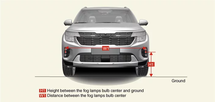
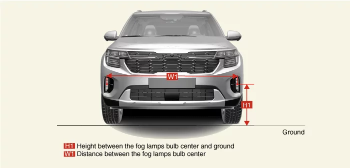
Draw vertical lines (Vertical lines passing through respective fog lamps centers) and a horizontal line (Horizontal line passing through center of fog lamps) on the screen.
With the fog lamp and battery in normal condition, aim the fog lamp so the brightest portion falls on the vertical lines.
[Standard Type]
A : Adjustment bolt
[Option Type]
A : Adjustment bolt
Fog Lamp Aiming Points
[Standard Type]
[2WD]
Vehicle Condition
H1
W1
Dimension
Empty
500 (19.69)
1,547 (60.91)
mm (in.)
1 person on-board
495 (19.49)
[4WD]
Vehicle Condition
H1
W1
Dimension
Empty
506 (19.92)
1,547 (60.91)
mm (in.)
1 person on-board
501 (19.72)
[Option Type]
[2WD]
Vehicle Condition
H1
W1
Dimension
Empty
480 (18.90)
1,554 (61.18)
mm (in.)
1 person on-board
475 (18.70)
[4WD]
Vehicle Condition
H1
W1
Dimension
Empty
486 (19.13)
1,554 (61.18)
mm (in.)
1 person on-board
481 (18.94)
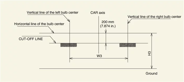
Turn the front fog lamp on without the driver aboard.
The cut-off line should be projected in the allowable range (shaded region).
Hazard Switch Removal and Installation
Removal
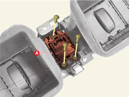
Remove the crash pad center air vent. (Refer to Body - "Crash Pad Air Vent")
Remove the hazard switch (A) after removing the screws.
Installation
Install in reverse order of removal.
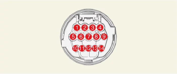
Headlamps Terminal Function
Connector and Terminal Function
[Headlamps]
Terminal
Function
Standard Type
Option Type
1
Low beam / high beam ( + )
Low beam ( + ) LED
2
-
High beam ( + ) LED
3
Turn signal lamp ( + )
Turn signal lamp ( + ) LED
4
-
Battery ( + )
5
Low beam / high beam ground ( - )
-
6
Leveling device ground ( - )
Leveling device ground ( - )
7
DRL / position lamp ground ( - )
-
8
Turn signal lamp ground ( - )
Battery ( - )
9
Position lamp ( + )
Position lamp ( + ) LED
10
DRL ( + )
DRL ( + ) LED
11
Leveling device ( - )
Leveling device ground ( + )
12
Leveling device signal
Leveling device signal
13
DC motor ( + )
Low beam tell-tail
14
DC motor ground ( - )
Turn signal lamp tell-tail
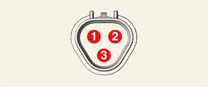
[Front Auxiliary Lamp]
Terminal
Fuction
1
Position lamp ( + ) RH
2
Position lamp ( + ) LH
3
Ground ( - )
Headlamps Removal and Installation
Removal
[Headlamps]
Remove the front bumper assembly. (Refer to Body - "Front Bumper Assembly")
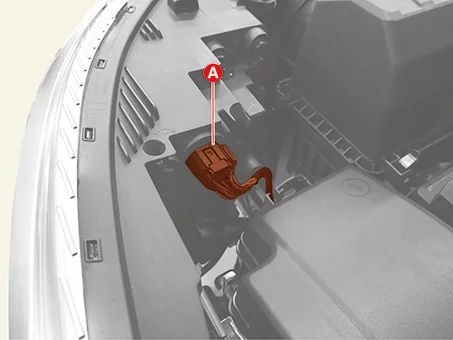
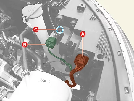
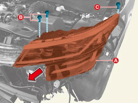
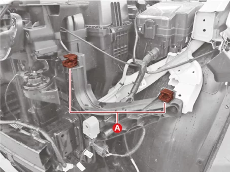
Disconnect the headlamp connector. [Driver's side] Disconnect the headlamp connector (A). [Passenger's side] Disconnect the headlamp connector (A), connector (B) and remove the wiring clip (C).
Remove the headlamp (A) in the direction of the arrow after removing the bolts. Tightening torque : Bolt (B) : 11.8 - 15,7 N·m Bolt (C) : 23.5 - 34 N·m
Be careful not to damage the clips (A).
Remove the radiator grille upper garnish. (Refer to Body - "Front Bumper Assembly")
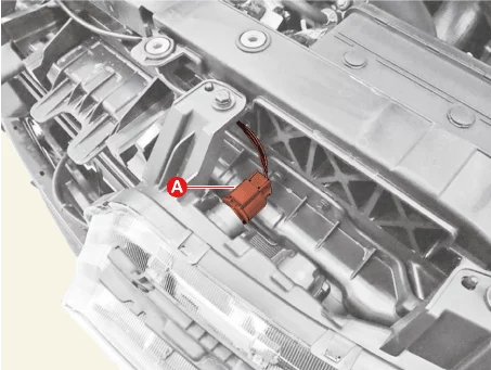
Disconnect the front auxiliary lamp connector (A).
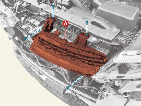
Remove the front auxiliary lamp (A) after removing the bolts.
[Front Auxiliary Lamp]
Installation
Install in reverse order of removal.
If the headlamp needs to be adjusted, refer to headlamp aiming procedure. (Refer to Headlamps - "Adjustment")
Headlamps Replacement
Replacement
Bulb
[Low Beam / High Beam]
Disconnect the negative ( - ) battery terminal.
Remove the headlamps. (Refer to Lighting System - "Headlamps")
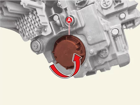
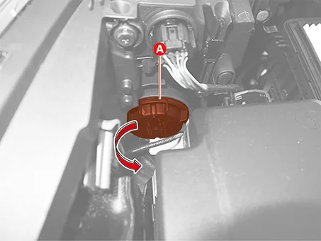
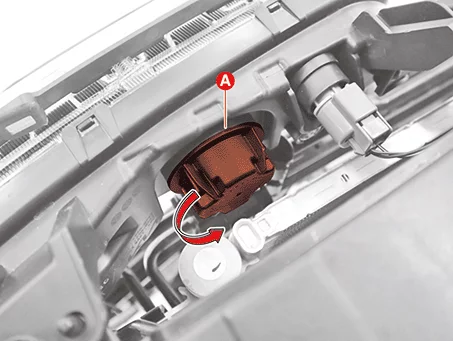
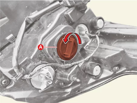
Remove the dust cap (A) by turning in the counterclockwise direction.
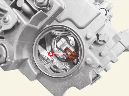
Disconnect the low beam / high beam connector (A).
Remove the low beam / high beam bulb socket by turning in the counterclockwise direction.
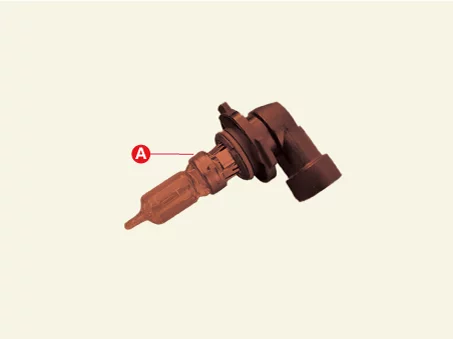
Replace the low beam / high beam bulb (A).
Install in reverse order of removal.
[Turn Signal Lamp]
Disconnect the negative ( - ) battery terminal.
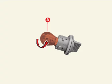
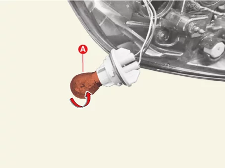
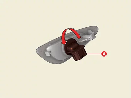
Remove the turn signal lamp bulb socket (A) by turning in the counterclockwise direction.
Replace the turn signal lamp bulb (A).
Install in reverse order of removal.
Absorbent
[Headlamp]
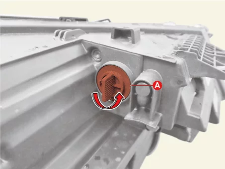
Remove the dust cap (A) by turning in the counterclockwise direction.
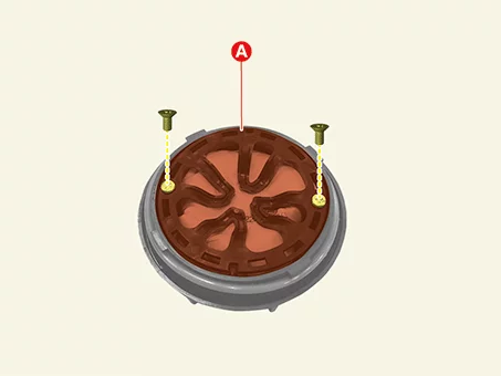
Remove the absorbent bracket (A) after removing the screws.
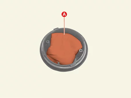
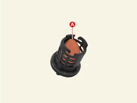
Replace the absorbent (A).
Fold the new absorbent material as the picture below.
Install in reverse order of removal.
[Front Auxiliary Lamp]
Remove the dust cap (A) by turning in the counterclockwise direction.
Remove the absorbent bracket (A) after removing the screws.
Replace the absorbent (A).
Fold the new absorbent material as the picture below.
Install in reverse order of removal.
Headlamps Adjustment
Adjustment
Headlamp Aiming Turn the adjusting gear to adjust the headlamp aiming. If beam-setting equipment is not available, proceed as follows.
Inflate the tires to the specified pressure and remove any loads from the vehicle except the driver, spare tire, and tools.
The vehicle should be placed on a flat floor.
Check if there is something wrong with the suspension spring.
Clean the headlamp lens.
Draw vertical lines (Vertical lines passing through respective headlamp centers) and a horizontal line (Horizontal line passing through center of headlamps) on the screen.
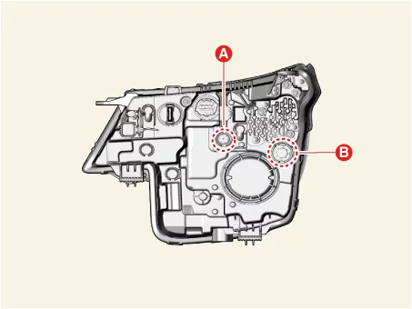
With the headlamp and battery in normal condition, aim the headlamps so the brightest portion falls on the horizontal and vertical lines. [Standard Type]
A : Vertical (High/Low beam)
B : Horizontal (High/Low beam)
[Option 1 Type]
A : Vertical (High/Low beam)
B : Horizontal (High/Low beam)
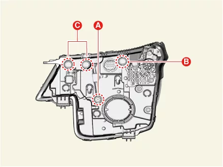
[Option 2 Type]
A : Vertical (High/Low beam)
B : Horizontal (Low beam)
C : Horizontal (High beam)
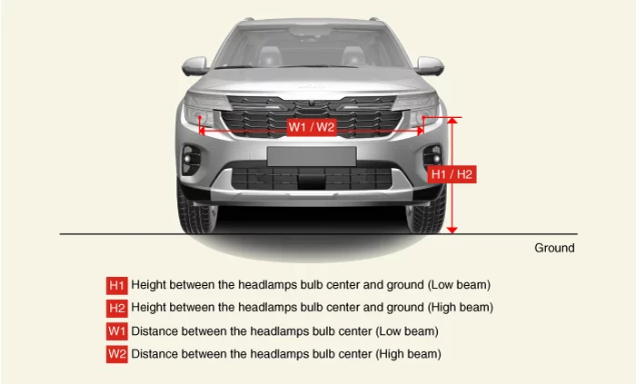
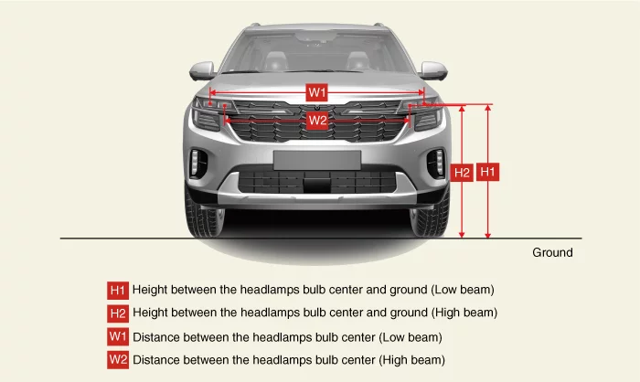
Headlamp Aiming Points
[Standard / Option 1 Type]
[2WD]
Vehicle Condition
H1
H2
W1
W2
Dimension
Empty
757 (29.80)
757 (29.80)
1,438 (56.61)
1,438 (56.61)
mm (in.)
1 person on-board
752 (29.60)
752 (29.60)
[4WD]
Vehicle Condition
H1
H2
W1
W2
Dimension
Empty
763 (30.04)
763 (30.04)
1,438 (56.61)
1,438 (56.61)
mm (in.)
1 person on-board
758 (29.84)
758 (29.84)
[Option 2 Type]
[2WD]
Vehicle Condition
H1
H2
W1
W2
Dimension
Empty
854(33.62)
844 (33.23)
1,373 (54.06)
1,169 (46.02)
imm (in.)
1 person on-board
849 (33.42)
839 (33.03)
[4WD]
Vehicle Condition
H1
H2
W1
W2
Remark
Empty
860 (33.86)
850 (33.46)
1,373 (54.06)
1,169 (46.02)
mm (in.)
1 person on-board
855 (33.66)
845 (33.27)
[Low Beam]
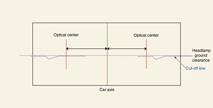
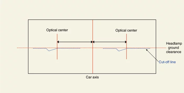
VOR Type (Visually Optically aimed using the Right side of the low beam) :Draw a horizontal line at -0.2% from the headlamp ground clearance.
Turn on to low beam the check the up-down/left-right aiming position.
Up-down Aiming : Match the cut-off line -0.2% line on the screen.
Left-Right Aiming : Match the left-right aiming point to the vertical line of optical center on the screen.
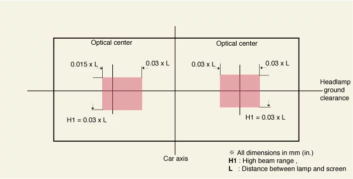
[High Beam ]
High beam hot point must be checked after low beam aiming. (No in-line aiming)
If high beam hot point deviates from below hot zone (RED BOX) after low beam aiming, this is because of defective lamps or damage and it should be inspected further or replace as needed.
High Mounted Stop Lamp Removal and Installation
Removal
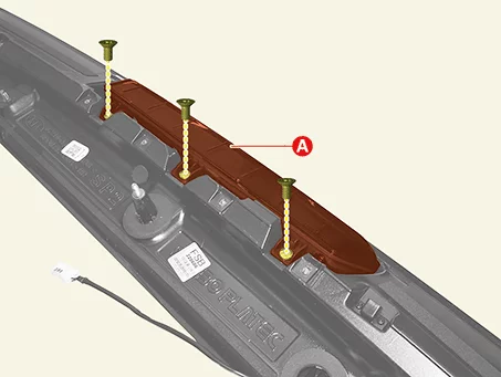
Remove the rear spoiler. (Refer to Body - "Rear Spoiler")
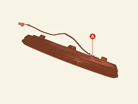
Remove the high mounted stop lamp (A) after removing the screws.
Installation
Install in reverse order of removal.
License Lamp Removal and Installation
Removal
Remove the tailgate outside handle. (Refer to Body - "Tailgate Outside Handle")
Installation
Install in reverse order of removal.
License Lamp Replacement
Replacement
Bulb
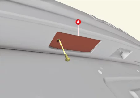
Remove the license lamp lens (A) after removing the screw.
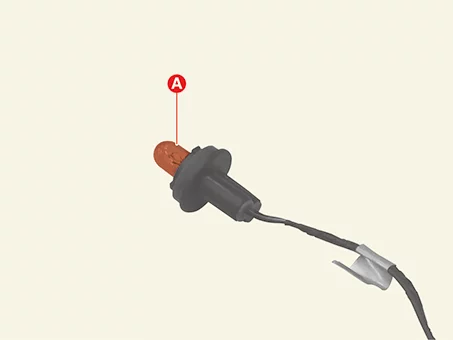
Replace the license lamp bulb (A).
Install in reverse order of removal.
Luggage Lamp Removal and Installation
Removal
Disconnect the negative ( - ) battery terminal.
Remove the luggage lamp (A) by using the remover.
Disconnect the luggage lamp connector (A).
Installation
Install in reverse order of removal.
Luggage Lamp Replacement
Replacement
Bulb
Remove the luggage lamp. (Refer to Lighting System - "Luggage Lamp")
Remove the luggage lamp lens (A) by pushing the hook in the direction of the arrow.
Replace the luggage lamp bulb (A).
Install in reverse order of removal.
Mood Lamp Removal and Installation
Removal
Mood Lamp Unit
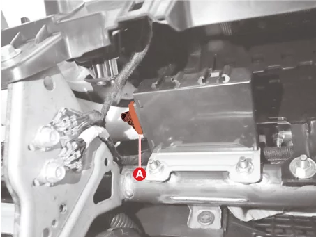
Remove the crash pad center panel. (Refer to Body - "Crash Pad Lower Panel")
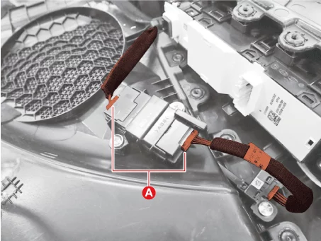
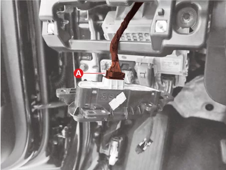
Disconnect the mood lamp unit connector (A).
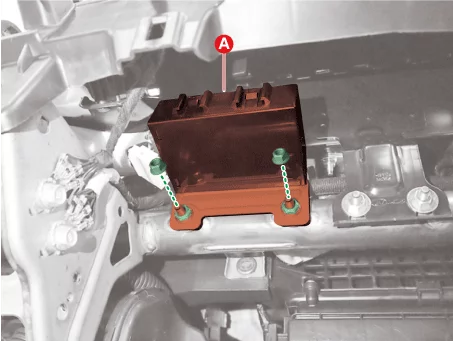
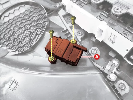
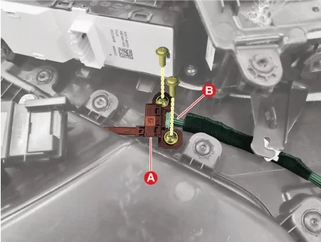
Remove the mood lamp unit (A) after removing the nuts.
Mood Lamp
Crash Pad Garnish
Remove the crash pad garnish [Passenger's side]. (Refer to Body - "Crash Pad Lower Panel")
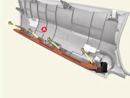
Remove the mood lamp.
Remove the mood lamp (A) after removing the screws.
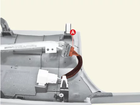
Disconnect the mood lamp connector (A).
Front Door Trim
[Mood Lamp 1]
Remove the front door trim. (Refer to Body - "Front Door Trim")
Remove the mood lamp.
Disconnect the mood lamp connectors (A).
Remove the mood lamp (A) after removing the screws.
Remove the front door trim. (Refer to Body - "Front Door Trim")
Remove the mood lamp.
Disconnect the mood lamp connector (B).
Remove the mood lamp (A) after removing the screws.
[Mood Lamp 2]
Installation
Install in reverse order of removal.
Overhead Console Lamp Terminal Function
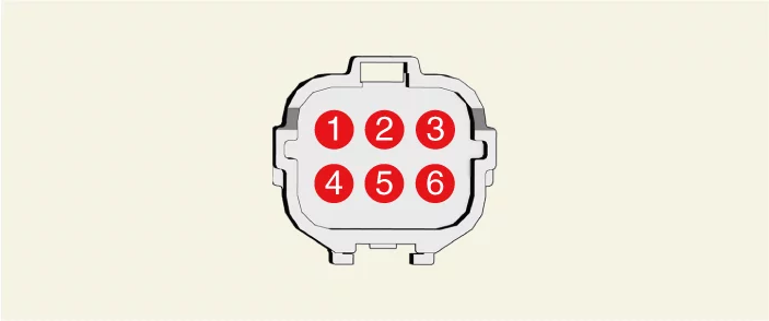
Connector and Terminal Function
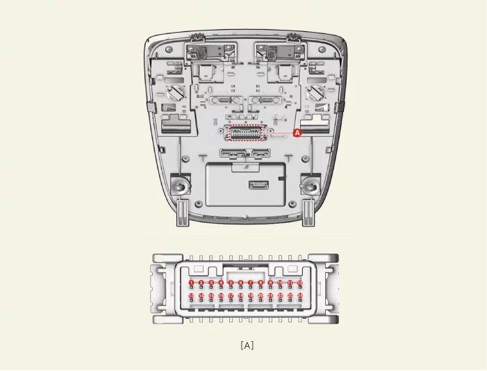
[A Type]
Connector A
Terminal
Function
Terminal
Function
1
Battery (+)
13
-
2
Airbag warning lamp
14
-
3
Illumination ( - )
15
-
4
-
16
-
5
Built-in cam IND
17
-
6
-
18
Room lamp signal
7
MTS keypad signal
19
Room lamp signal (Output)
8
IG 1
20
-
9
Ground
21
-
10
Built-in cam signal
22
-
11
PAB off IND
23
-
12
Ground
24
-
[B Type]
Connector A
Terminal
Function
Terminal
Function
1
Battery (+)
17
-
2
Airbag warning lamp
18
-
3
Illumination ( - )
19
-
4
-
20
-
5
Built-in cam IND
21
-
6
-
22
Room lamp signal
7
MTS keypad signal
23
-
8
IG 1
24
-
9
Ground
25
-
10
Built-in cam signal
26
-
11
-
27
-
12
-
28
-
13
Ground
29
-
14
-
30
-
15
PAB off IND
31
-
16
Door signal
32
-
Overhead Console Lamp Removal and Installation
Removal
Disconnect the negative ( - ) battery terminal.
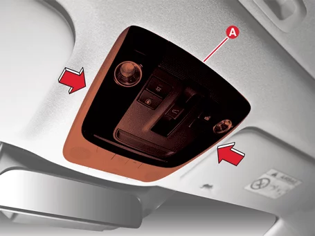
Remove the overhead console lamp (A) by using the remover.
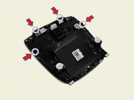
Clip position :
Replace any damaged clips.
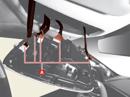
Disconnect the overhead console lamp connectors (A).
Installation
Install in reverse order of removal.
Overhead Console Lamp Inspection
Inspection
Remove the overhead console lamp. (Refer to Lighting System - "Overhead Console Lamp")
Check for continuity between terminals.
Terminal
Switch OFF
Switch ON
13 - 22
No continuity
Continuity
Rear Combination Lamp Terminal Function
Connector and Terminal Function
[Outside Rear Combination Lamp]
Terminal
Function
Standard Type
Option Type
1
Tail lamp ( + )
Tail lamp ( + )
2
Stop lamp ( + )
Stop lamp ( + )
3
Turn signal lamp ( + )
Turn signal lamp ( + )
4
-
Stop lamp ( + ) LED
5
-
Ground
6
Ground
-
[Inside Rear Combination Lamp]
Terminal
Function
1
Ground
2
Tail lamp ( + )
Rear Combination Lamp Removal and Installation
Removal
[Outside Rear Combination Lamp]
Disconnect the negative ( - ) battery terminal.
Remove the mounting screws (A).
Remove the outside rear combination lamp (A) in the direction of the arrow.
Disconnect the outside rear combination lamp connector (A).
[Inside Rear Combination Lamp]
Disconnect the negative ( - ) battery terminal.
Remove the tailgate lid lower trim. (Refer to Body - " Tailgate Lid Trim")
Disconnect both inside rear combination lamp connectors (A).
Disconnect the license lamp connector (A).
Remove the nuts (A).
Remove the inside rear combination lamp (A).
Installation
Install in reverse order of removal.
Rear Combination Lamp Replacement
Replacement
Bulb
[Turn Signal Lamp]
Remove the outside rear combination lamp. (Refer to Lighting System - "Rear Combination Lamp")
Remove the turn signal lamp bulb socket (A) by turning in the counterclockwise.
Remove the turn signal lamp bulb (A) by turning in the counterclockwise.
Install in reverse order of removal.
[Tail/Stop Lamp]
Remove the outside rear combination lamp. (Refer to Lighting System - "Rear Combination Lamp")
Remove the tail/stop lamp bulb socket (A) by turning in the counterclockwise.
Remove the tail/stop lamp bulb by turning in the counterclockwise.
Absorbent
Remove the outside rear combination lamp. (Refer to Lighting System - "Rear Combination Lamp")
Remove the dust cap (A) by turning in the counterclockwise.
Remove the cover (A) by pressing it in the direction of the arrow and then turning it counterclockwise.
Replace the absorbent (A).
Fold the new absorbent material as the picture below.
Install in reverse order of removal.
Rheostat Removal and Installation
Removal
Remove the crash pad lower panel. (Refer to Body - "Crash Pad Lower Panel")
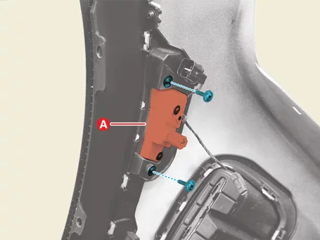
Remove the crash pad side switch (A) after removing the screws.
Disconnect the crash pad side switch connector (A).
Installation
Install in reverse order of removal.
Room Lamp Removal and Installation
Removal
Disconnect the negative ( - ) battery terminal.
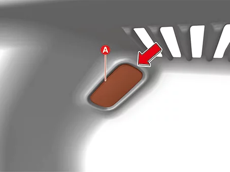
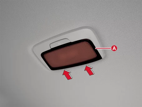
Remove the room lamp(A) by using the remover.
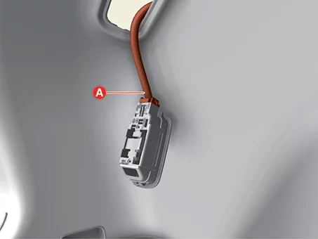
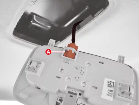
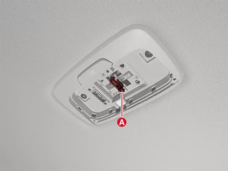
Disconnect the room lamp connector (A).
Installation
Install in reverse order of removal.
Room Lamp Replacement
Replacement
Bulb
Disconnect the negative ( - ) battery terminal.
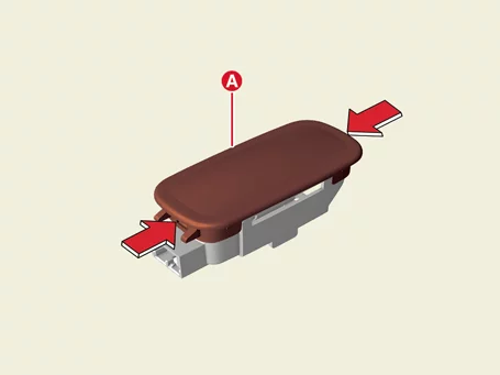
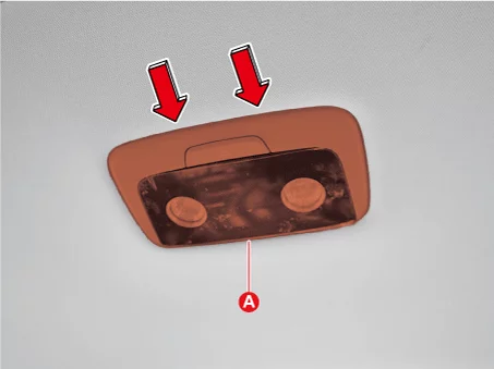
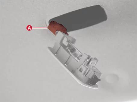
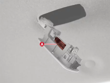
Remove the room lamp cover (A) by using the remover.
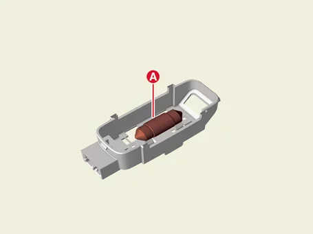
Replace the room lamp bulb (A).
Install in reverse order of removal.
Side Mark Lamp Removal and Installation
Removal
Remove the front bumper assembly. (Refer to Body - "Front Bumper Assembly")
Disconnect the side mark lamp connector (A).
Remove the side mark lamp (A) after removing the screws.
Installation
Install in reverse order of removal.
Side Mark Lamp Replacement
Replacement
Remove the front bumper assembly. (Refer to Body - "Front Bumper Assembly")
Disconnect the side mark lamp connector (A).
Remove the side mark lamp socket (A).
Replace the side mark lamp bulb (A).
Turn Signal Lamp Removal and Installation
Removal
Side Repeater Lamp [Fender]
Disconnect the battery negative ( - ) terminal.
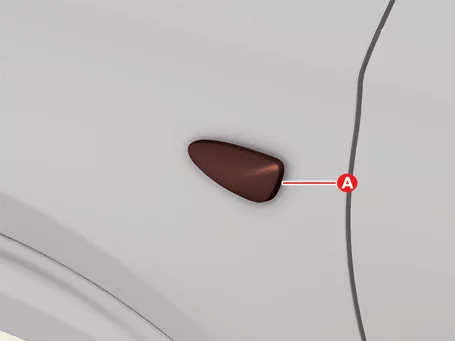
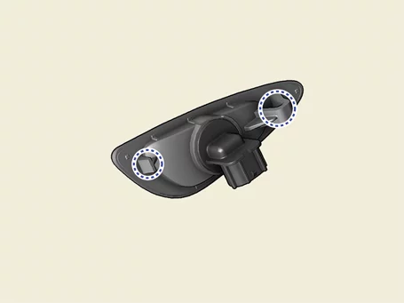
Remove the side repeater lamp (A) by pressing the hook in the direction of the arrow.
Clip position :
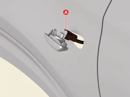
Disconnect the side repeater lamp connector (A).
Remove the outside view mirror lower scalp. (Refer to Body - "Outside Rear View Mirror")
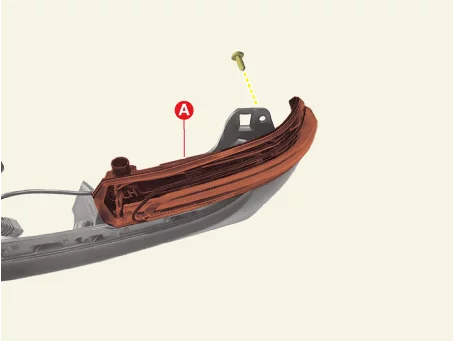
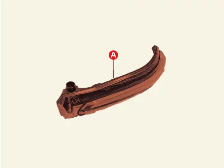
Remove the turn signal lamp (A) after removing the screw.
Side Repeater Lamp [Outside Mirror]
Installation
Install in reverse order of removal.
Turn Signal Lamp Replacement
Replacement
[Bulb]
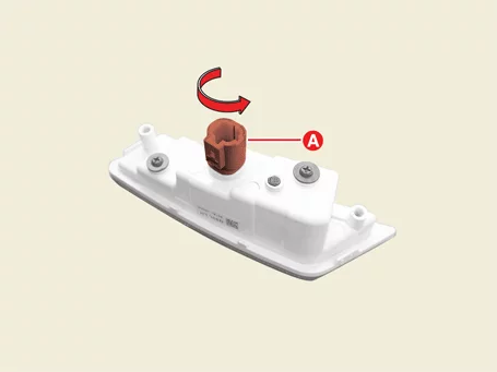
Remove the side repeater lamp [Fender]. (Refer to Lighting System - "Trun Signal Lamp")