Body Electrical System
Head Up Display (HUD) System
In this manual: Body Electrical System
13steps
~78min
3/5difficulty
Done 0 of 13
Contents:
Description and Operation
Description
Head-Up Display (HUD) System displays various information on the windshield glass which minimizes the driver’s eye movement to enhance safety and convenience. Information provided by HUD- Drive information : Vehicle speed, Drive mode
- Turn by Turn navigation information, road signs, over speed.
- Safety warning lamp : Smart Cruise Control (SCC), Lane Keeping Assist (LKA), Blind-Spot Collision Warning (BCW)
- Head-Up Display (HUD) : Output various vehicle system information on windshield glass via CAN communication.
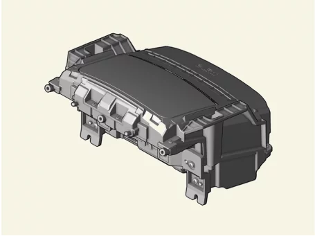
- HUD ON/OFF Switch Turn ON/OFF the HUD via the side crash pad switch.

- Illumination Sensor : It is equipped with bidirectional (A : vertical, B : horizontal) sensor. HUD brightness is controlled depending on horizontal measurement (ambient brightness).
- Built-in bidirectional illumination sensor
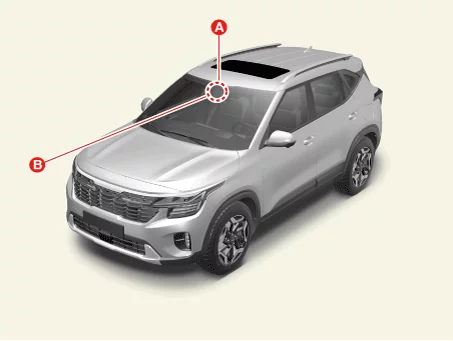
If illumination sensor measurement could not be detected, HUD will not be displayed. Check for normal operation of illumination sensor before inspecting HUD.
- Windshield glass : Windshield glass exclusive for Head-Up Display is built in with double image removal film.
- Use of window tinting film on windshield glass may decrease image quality.
- Image may be distorted or seem dark if driver wears polarized sunglasses.
When replacing front windshield glass, always replace with exclusive windshield glass for Head-Up Display (HUD). Otherwise, the Head-Up Display (HUD) images may overlap.
Troubleshooting
Troubleshooting
| Item | Symptoms | Check List | Detail | Components |
| Lighting |
|
|
|
Illumination sensor CGW Cluster |
| Adjustment function |
|
|
|
AVNT |
Head Up Display (HUD) Unit On Vehicle Inspection
On Vehicle Inspection
Diagnosis with KDS
- The Head-Up Display (HUD) can be more quickly diagnosed for problems with the KDS (Refer to "DTC guide").
- Self diagnosis : Inspect the Diagnostic Trouble Code (DTC) with the KDS. (Refer to DTC guide when fault code is found.)
- S/W Management : Controlling other features including system option setting and zero point adjustment. (S/W Management → Head-Up Display → HUD Calibration)
Refer to the KDS screen for operating conditions and details.
Head Up Display (HUD) Unit Terminal Function
Connector and Terminal Function
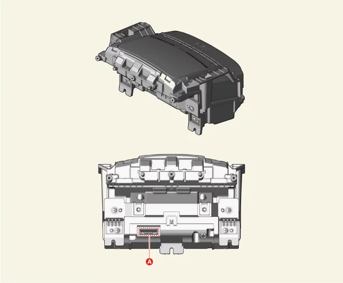
| Connector A | Terminal | Function | Terminal | Function |
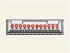 |
1 | - | 7 | C-CAN (High) |
| 2 | Battery (+) | 8 | C-CAN (Low) | |
| 3 | IG 1 | 9 | - | |
| 4 | - | 10 | HUD switch | |
| 5 | M-CAN (High) | 11 | Ground | |
| 6 | M-CAN (Low) | 12 | Ground |
Head Up Display (HUD) Unit Removal and Installation
Removal
- Remove the cluster. (Refer to Instrument Cluster - "Cluster")
- Disconnect the Head-Up Display (HUD) unit connector (A).
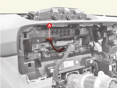
- Remove the Head-Up Display (HUD) unit (A) after removing the nuts.

Installation
- Install in reverse order of removal.
Head Up Display (HUD) Unit Adjustment
Adjustment
If a part of the Head-Up Display (HUD) footage is distorted or it is not at eye level with the driver a KDS can be used to perform calibration.- Calibration is required
- After replacing the head-up display unit
- When the footage is distorted after replacing the windshield (double vision removal film built-in glass)
- When the HUD mounted main crash pad is removed/installed or replaced
- When the image setting location of the HUD unit is not at eye level of the driver resulting in out of focus image
- Calibration items
No Footage calibration functions 1 Horizontal rotation 2 Upward/downward 3 Slope (up / down) 4 Parallel slope 5 Vertical movement 6 Slope (left / right) calibration 7 Width calibration 8 Height calibration 9 Initialization: Return to previous status before calibration - Process of calibration
- Locate the vehicle on a flat plane for accurate adjustment.
- Make sure that there are no foreign materials on the windshield.
- Perform the "HUD Calibration" by using KDS. (S/W Management → Head-Up Display → HUD Calibration)
'HUD calibration - initialization' must be performed prior to 'calibration'.
Refer to the KDS screen for operating conditions and details. - When calibration is completed, start and turn off the engine and check that the footage calibration is completed.
Was this page helpful?