Body Electrical System
Power Door Locks
In this manual: Body Electrical System
17steps
~102min
4/5difficulty
Done 0 of 17
Contents:
Power Door Look Module Removal and Installation
Removal
Front Door Lock Module- Remove the front door latch. (Refer to Body - "Front Door Latch")
- Remove the rear door latch. (Refer to Body - "Rear Door Latch")
- Remove the tailgate latch. (Refer to Body - "Tailgate Latch")
- Remove the hood latch. (Refer to Body - "Hood Latch Assembly")
Installation
- Install in reverse order of removal.
Power Door Look Module Inspection
Inspection
Front Door Lock Module- Remove the front door module. (Refer to Body - "Front Door Module")
- Disconnect the connector from the door lock module.
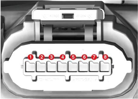
Terminal Function LH RH 1 - Motor (CL) 2 - Motor (COM) 3 Switch (COM) - 4 Lock/Unlock Switch (AJAR) 5 Switch (AJAR) Lock/Unlock 6 - Switch (COM) 7 Motor (COM) - 8 Motor (CL) - - Apply battery voltage to each terminal as shown in the table and verify that the mirror operates properly. [LH]
Terminal Function Central Lock Central Unlock 8 + - 7 - + 3 - 4 ON → OFF OFF → ON 3 - 5 Door open & half latching : ON
Full latching : OFF
[RH]Terminal Function Central Lock Central Unlock 1 + - 2 - + 6 - 5 ON → OFF OFF → ON 6 - 4 Door open & half latching : ON
Full latching : OFF - Remove the rear door module. (Refer to Body - "Rear Door Module")
- Disconnect the connector from the rear door lock module.
Terminal Function LH RH 1 - Motor (CL) 2 - Motor (COM) 3 Switch (COM) - 4 Lock/Unlock Switch (AJAR) 5 Switch (AJAR) Lock/Unlock 6 - Switch (COM) 7 Motor (COM) - 8 Motor (CL) -
[Power Child Lock]Terminal Function LH RH 1 Switch (PCL) Motor (CL) 2 Switch (COM) Motor (COM) 3 Lock/Unlock COM (PCL) 4 Switch (AJAR) Motor (PCL) 5 COM (PCL) Switch (AJAR) 6 Motor (PCL) Lock/Unlock 7 Motor (COM) Switch (COM) 8 Motor (CL) Switch (PCL) - Apply battery voltage to each terminal as shown in the table and verify that the mirror operates properly. [LH]
Terminal Function Central Lock Central Unlock 8 + - 7 + - 2 - 3 ON → OFF OFF → ON 2 - 4 Door open & half latching : ON
Full latching : OFF
[RH]Terminal Function Central Lock Central Unlock 1 + - 2 - + 7 - 6 ON → OFF OFF → ON 7 - 5 Door open & half latching : ON
Full latching : OFF - Remove the tailgate lid trim. (Refer to Body - " Tailgate Lid Trim")
- Disconnect the tailgate latch connector. [Power Tailgate]
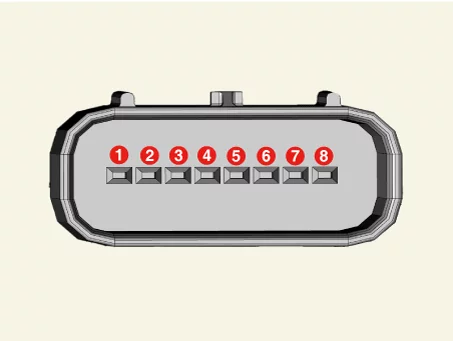
Terminal Function 1 Motor ( - ) 2 Motor ( + ) 3 Switch (REF) 4 COM 5 Switch (AJAR) 6 Switch (HOME) 7 COM 8 Switch (PAWL) - Apply battery voltage to each terminal as shown in the table and verify that the mirror operates properly. 1) Lock
Terminal Function Unlatching Unlatching → Half Latching Half Latching→ Full Latching Full Latching → Return Return Position 2 X - - + X 1 + + - 7 - 8 ON ON → OFF OFF OFF OFF 6 - 7 ON ON ON ON → OFF OFF 4 - 5 ON ON ON → OFF OFF OFF 3 - 4 ON ON ON → OFF OFF OFF
2) OpenTerminal Function Unlatching Full Latching → Unlatching Unlatching → Return Return Position 2 X + - X 1 - + 7 - 8 OFF OFF → ON ON ON 6 - 7 OFF OFF → ON ON → OFF OFF → ON 4 - 5 OFF OFF → ON ON ON 3 - 4 OFF OFF → ON ON ON
[Non-Power Tailgate]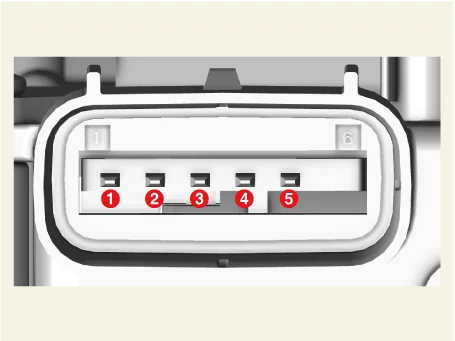
Terminal Function Full Lock Half Lock Full Open 1 + + X 3 - - X 2 - 4 OFF OFF ON 5 - 4 OFF ON ON - Remove the hood latch assembly. (Refer to Body - "Hood Latch Assembly")
- Check for continuity between terminals No. 1 and No. 2. If there is no continuity, replace the hood latch switch.
Power Door Lock Switch Removal and Installation
Removal
[Driver's Side]- Remove the power window main switch assembly. (Refer to Power Window - "Power Window Switch" )
- Remove the power window sub switch assembly. (Refer to Power Window - "Power Window Switch" )
Installation
- Install in reverse order of removal.
Was this page helpful?