Body Electrical System
Immobilizer System
In this manual: Body Electrical System
10steps
~60min
3/5difficulty
Done 0 of 10
Contents:
Description and Operation
Description and Operation
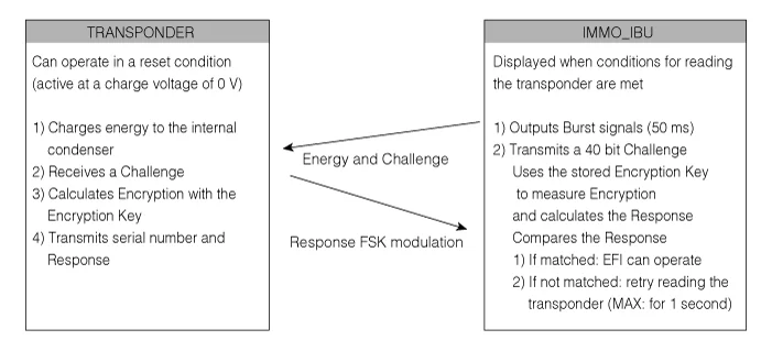
- The immobilizer system prevents vehicle theft by keeping the engine from starting without a registered key.
- The engine starts only when the codes of ECM (Engine Control Module), IBU (Integrated Body Control Unit) and smart key are identical. If the key is not the genuine key for the vehicle, the fuel supply is cut off and the engine does not start.
|

- Control Procedure During Vehicle Access
- If the driver carries the smart key and accesses the vehicle door, the smart key receives LF signals from the LF antenna and then sends RF signals to RF antenna.
- The RF antenna sends the RF signals to the IBU (Integrated Body Control Unit).
- After receiving the signals, if the key data matches, the IBU signals the ICU (Integrated Central Control Unit) to release the door lock.
- The ICU controls the door lock actuator depending on the door unlock signal of the IBU to unlock the door.
- Control Procedure During Engine Start After Vehicle Entry
- When the driver presses the brake pedal and the engine start button, the start and brake signals are sent to the IBU (Integrated Body Control Unit) and the IBU operates the LF antenna.
- The LF antenna sends key data LF signals. The smart key receives the LF signals and then sends the RF signals to the RF antenna.
- The RF antenna sends the RF signals to the IBU, and the IBU starts K-Line (Immobilizer) communication with the ECM (Engine Control Module).
- The IBU authenticates through the K-Line (Immobilizer) communication with the ECM. If the data matches, the engine starts.

|

On Vehicle Inspection
On Vehicle Inspection
Diagnosis with KDS
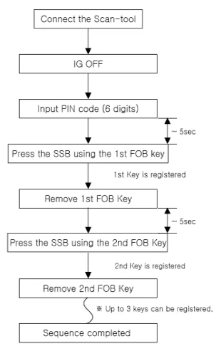
- The immobilizer system can be more quickly diagnosed for problems with the KDS (Refer to "DTC guide").
- Self diagnosis : Inspect the Diagnostic Trouble Code (DTC) with the KDS. (Refer to DTC guide when fault code is found.)
- S/W Management : Controlling other features including system option setting and zero point adjustment. (S/W Management → Integrated Body Control Unit-IMMO → Neutral Mode) (S/W Management → Integrated Body Control Unit - IMMO → LEARNT KEYS) (S/W Management → Integrated Body Control Unit - IMMO → Password Teaching/Changing) (S/W Management → Integrated Body Control Unit - IMMO → Limp Home Mode)
Refer to the KDS screen for operating conditions and details.
Immobilizer Control Unit Removal and Installation
Removal
- Remove the Integrated Body Control Unit (IBU). (Refer to Integrated Body Control Unit (IBU) - "Removal and Installation")
Installation
- Install in reverse order of removal.
Antenna Coil Removal and Installation
Removal
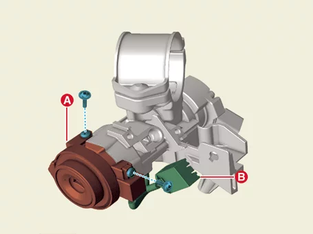
- Remove the steering column shroud panel. (Refer to Body - "Steering Column Shroud Panel")
- Remove the antenna coil (A) by removing the screws after disconnecting the coil antenna connector (B).
Installation
- Install in reverse order of removal.
Was this page helpful?