Outer Mirror Switch
Components
COMPONENTS
ILLUSTRATION
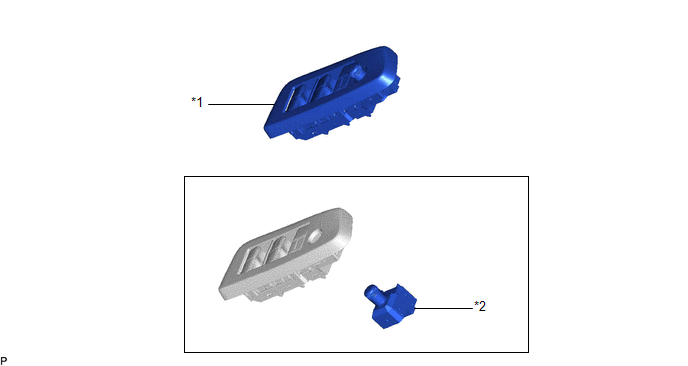
*1 |
MULTIPLEX NETWORK MASTER SWITCH ASSEMBLY WITH FRONT DOOR UPPER ARMREST BASE PANEL |
*2 |
OUTER MIRROR SWITCH ASSEMBLY |
Inspection
INSPECTION
PROCEDURE
1. INSPECT OUTER MIRROR SWITCH ASSEMBLY (w/o Memory)
(a) Check the mirror select switch and mirror surface adjust switch.
(1) Turn the mirror select switch to the L position. |
|
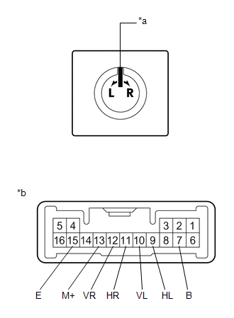
(2) Measure the resistance according to the value(s) in the table below.
Standard Resistance (for left side):
Tester Connection | Condition | Specified Condition |
|---|---|---|
10 (VL) - 7 (B) 13 (M+) - 15 (E) |
Up |
Below 2 Ω |
Off |
10 kΩ or higher |
|
10 (VL) - 15 (E) 13 (M+) - 7 (B) |
Down |
Below 2 Ω |
Off |
10 kΩ or higher |
|
9 (HL) - 7 (B) 13 (M+) - 15 (E) |
Left |
Below 2 Ω |
Off |
10 kΩ or higher |
|
9 (HL) - 15 (E) 13 (M+) - 7 (B) |
Right |
Below 2 Ω |
Off |
10 kΩ or higher |
(3) Turn the mirror select switch to the R position.
(4) Measure the resistance according to the value(s) in the table below.
Standard Resistance (for right side):
Tester Connection | Condition | Specified Condition |
|---|---|---|
12 (VR) - 7 (B) 13 (M+) - 15 (E) |
Up |
Below 2 Ω |
Off |
10 kΩ or higher |
|
12 (VR) - 15 (E) 13 (M+) - 7 (B) |
Down |
Below 2 Ω |
Off |
10 kΩ or higher |
|
11 (HR) - 7 (B) 13 (M+) - 15 (E) |
Left |
Below 2 Ω |
Off |
10 kΩ or higher |
|
11 (HR) - 15 (E) 13 (M+) - 7 (B) |
Right |
Below 2 Ω |
Off |
10 kΩ or higher |
If the result is not as specified, replace the outer mirror switch assembly.
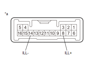
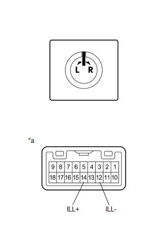
(b) Check that the LED illuminates.
(1) Apply auxiliary battery voltage to the outer mirror switch assembly and check that the LED illuminates. OK:
If the result is not as specified, replace the outer mirror switch assembly. |
|
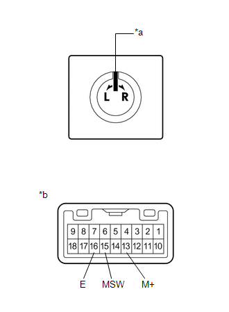
2. INSPECT OUTER MIRROR SWITCH ASSEMBLY (w/ Memory)
(a) Check the mirror select switch and mirror surface adjust switch.
(1) Measure the resistance according to the value(s) in the table below. Standard Resistance:
If the result is not as specified, replace the outer mirror switch assembly. |
|
(b) Check that the LED illuminates.
(1) Apply auxiliary battery voltage to the outer mirror switch assembly and check that the LED illuminates. OK:
If the result is not as specified, replace the outer mirror switch assembly. |
|
Installation
INSTALLATION
PROCEDURE
1. INSTALL OUTER MIRROR SWITCH ASSEMBLY
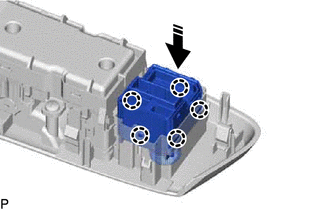
(a) Engage the 5 claws to install the outer mirror switch assembly as shown in the illustration.
 |
Install in this Direction |
2. INSTALL MULTIPLEX NETWORK MASTER SWITCH ASSEMBLY WITH FRONT DOOR UPPER ARMREST BASE PANEL
Click here 
Removal
REMOVAL
PROCEDURE
1. REMOVE MULTIPLEX NETWORK MASTER SWITCH ASSEMBLY WITH FRONT DOOR UPPER ARMREST BASE PANEL
Click here 
2. REMOVE OUTER MIRROR SWITCH ASSEMBLY
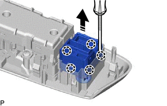
(a) Using a screwdriver, disengage the 5 claws and remove the outer mirror switch assembly as shown in the illustration.
 |
Remove in this Direction |