Power Mirror Control System(for Hv Model With Memory)
Customize Parameters
CUSTOMIZE PARAMETERS
CUSTOMIZE POWER MIRROR CONTROL SYSTEM (w/ Memory)
NOTICE:
- When the customer requests a change in a function, first make sure that the function can be customized.
- Record the current settings before customizing.
HINT:
The following items can be customized.
(a) Customizing with the Techstream
(1) Connect the Techstream to the DLC3.
(2) Turn the power switch on (IG).
(3) Turn the Techstream on.
(4) Enter the following menus: Customize Setting / Others.
(5) Select the setting by referring to the table below.
OthersTester Display | Description | Default | Setting | ECU |
|---|---|---|---|---|
Auto Fold Mirror |
Function that changes the condition under which the outer mirrors automatically retract* |
Door Lock |
01:ACC,10:Door Lock,11:OFF |
Main body ECU (Multiplex network body ECU) |
Reverse Coupled Actuation Mirror Angle |
Function that turns the reverse shift-linked mirror position memorization function on or off* |
User Setting |
0:Default Setting,1:User Setting |
Main body ECU (Multiplex network body ECU) |
- *: Although the item is displayed on the Techstream, it is not applicable to this vehicle.
Data List / Active Test
DATA LIST / ACTIVE TEST
DATA LIST
NOTICE:
In the table below, the values listed under "Normal Condition" are reference values. Do not depend solely on these reference values when deciding whether a part is faulty or not.
HINT:
Using the Techstream to read the Data List allows the values or states of switches, sensors, actuators and other items to be read without removing any parts. This non-intrusive inspection can be very useful because intermittent conditions or signals may be discovered before parts or wiring is disturbed. Reading the Data List information early in troubleshooting is one way to save diagnostic time.
(a) Connect the Techstream to the DLC3.
(b) Turn the power switch on (IG).
(c) Turn the Techstream on.
(d) Enter the following menus: Body Electrical / Mirror L, Mirror R or Main Body / Data List.
(e) Read the Data List according to the display on the Techstream.
Body Electrical > Mirror L > Data ListTester Display | Measurement Item | Range | Normal Condition | Diagnostic Note |
|---|---|---|---|---|
Seat Memory Switch1 |
Seat memory switch M1 switch signal |
OFF or ON |
OFF: Seat memory switch M1 switch off ON: Seat memory switch M1 switch on |
- |
Seat Memory Switch2 |
Seat memory switch M2 switch signal |
OFF or ON |
OFF: Seat memory switch M2 switch off ON: Seat memory switch M2 switch on |
- |
Seat Memory Switch3 |
Seat memory switch M3 switch signal* |
OFF or ON |
OFF: Seat memory switch M3 switch off ON: Seat memory switch M3 switch on |
Not applicable |
Seat Memory Set SW |
Seat memory switch SET switch signal |
OFF or ON |
OFF: Seat memory switch SET switch off ON: Seat memory switch SET switch on |
- |
Mirror Memory No.1 |
Mirror position memorized in memory switch M1 |
OFF or ON |
OFF: Not memorized ON: Memorized |
- |
Mirror Memory No.2 |
Mirror position memorized in memory switch M2 |
OFF or ON |
OFF: Not memorized ON: Memorized |
- |
Mirror Memory No.3 |
Mirror position memorized in memory switch M3* |
OFF or ON |
OFF: Not memorized ON: Memorized |
Not applicable |
Mirror Memory No.4 |
Mirror position memorized in memory switch M4* |
OFF or ON |
OFF: Not memorized ON: Memorized |
Not applicable |
Mirror Memory No.5 |
Mirror position memorized in memory switch M5* |
OFF or ON |
OFF: Not memorized ON: Memorized |
Not applicable |
Mirror Memory No.6 |
Mirror position memorized in memory switch M6* |
OFF or ON |
OFF: Not memorized ON: Memorized |
Not applicable |
Mirror Memory(Rev) No.1 |
Mirror reverse shift-linked position No. 1 memorized* |
OFF or ON |
OFF: Not memorized ON: Memorized |
Not applicable |
Mirror Memory(Rev) No.2 |
Mirror reverse shift-linked position No. 2 memorized* |
OFF or ON |
OFF: Not memorized ON: Memorized |
Not applicable |
Mirror Memory(Rev) No.3 |
Mirror reverse shift-linked position No. 3 memorized* |
OFF or ON |
OFF: Not memorized ON: Memorized |
Not applicable |
Mirror Vertical Sensor Vol |
Vertical mirror position |
MIN: 0, MAX: 5 V |
0 to 5 V |
- |
Mirror Horizontal Sensor Vol |
Horizontal mirror position |
MIN: 0, MAX: 5 V |
0 to 5 V |
- |
+B Voltage Input Value |
Power supply for outer mirror control ECU assembly |
MIN: 0 V, MAX: 25.5 V |
11 to 14 V |
- |
# Codes |
Number of trouble codes |
0 to 255 |
Number of stored DTCs displayed |
- |
- *: Although the item is displayed on the Techstream, it is not applicable to this vehicle.
Tester Display | Measurement Item | Range | Normal Condition | Diagnostic Note |
|---|---|---|---|---|
Seat Memory Switch1 |
Seat memory switch M1 switch signal |
OFF or ON |
OFF: Seat memory switch M1 switch off ON: Seat memory switch M1 switch on |
- |
Seat Memory Switch2 |
Seat memory switch M2 switch signal |
OFF or ON |
OFF: Seat memory switch M2 switch off ON: Seat memory switch M2 switch on |
- |
Seat Memory Switch3 |
Seat memory switch M3 switch signal* |
OFF or ON |
OFF: Seat memory switch M3 switch off ON: Seat memory switch M3 switch on |
Not applicable |
Seat Memory Set SW |
Seat memory switch SET switch signal |
OFF or ON |
OFF: Seat memory switch SET switch off ON: Seat memory switch SET switch on |
- |
Mirror Memory No.1 |
Mirror position memorized in memory switch M1 |
OFF or ON |
OFF: Not memorized ON: Memorized |
- |
Mirror Memory No.2 |
Mirror position memorized in memory switch M2 |
OFF or ON |
OFF: Not memorized ON: Memorized |
- |
Mirror Memory No.3 |
Mirror position memorized in memory switch M3* |
OFF or ON |
OFF: Not memorized ON: Memorized |
Not applicable |
Mirror Memory No.4 |
Mirror position memorized in memory switch M4* |
OFF or ON |
OFF: Not memorized ON: Memorized |
Not applicable |
Mirror Memory No.5 |
Mirror position memorized in memory switch M5* |
OFF or ON |
OFF: Not memorized ON: Memorized |
Not applicable |
Mirror Memory No.6 |
Mirror position memorized in memory switch M6* |
OFF or ON |
OFF: Not memorized ON: Memorized |
Not applicable |
Mirror Memory(Rev) No.1 |
Mirror reverse shift-linked position No. 1 memorized* |
OFF or ON |
OFF: Not memorized ON: Memorized |
Not applicable |
Mirror Memory(Rev) No.2 |
Mirror reverse shift-linked position No. 2 memorized* |
OFF or ON |
OFF: Not memorized ON: Memorized |
Not applicable |
Mirror Memory(Rev) No.3 |
Mirror reverse shift-linked position No. 3 memorized* |
OFF or ON |
OFF: Not memorized ON: Memorized |
Not applicable |
Mirror Vertical Sensor Vol |
Vertical mirror position |
MIN: 0, MAX: 5 V |
0 to 5 V |
- |
Mirror Horizontal Sensor Vol |
Horizontal mirror position |
MIN: 0, MAX: 5 V |
0 to 5 V |
- |
+B Voltage Input Value |
Power supply for outer mirror control ECU assembly |
MIN: 0 V, MAX: 25.5 V |
11 to 14 V |
- |
# Codes |
Number of trouble codes |
0 to 255 |
Number of stored DTCs displayed |
- |
- *: Although the item is displayed on the Techstream, it is not applicable to this vehicle.
Tester Display | Measurement Item | Range | Normal Condition | Diagnostic Note |
|---|---|---|---|---|
Mirror Selection SW (R) |
Mirror select switch signal for RH mirror |
OFF or ON |
OFF: Mirror select switch off ON: Mirror select switch R switch on |
- |
Mirror Selection SW (L) |
Mirror select switch signal for LH mirror |
OFF or ON |
OFF: Mirror select switch off ON: Mirror select switch L switch on |
- |
Mirror Position SW (R) |
Mirror adjust switch signal (Right) |
OFF or ON |
OFF: Mirror adjust switch not pushed right ON: Mirror adjust switch pushed right |
Check with the mirror select switch L or R selected |
Mirror Position SW (L) |
Mirror adjust switch signal (Left) |
OFF or ON |
OFF: Mirror adjust switch not pushed left ON: Mirror adjust switch pushed left |
Check with the mirror select switch L or R selected |
Mirror Position SW (Up) |
Mirror adjust switch signal (Up) |
OFF or ON |
OFF: Mirror adjust switch not pushed up ON: Mirror adjust switch pushed up |
Check with the mirror select switch L or R selected |
Mirror Position SW (Dwn) |
Mirror adjust switch signal (Down) |
OFF or ON |
OFF: Mirror adjust switch not pushed down ON: Mirror adjust switch pushed down |
Check with the mirror select switch L or R selected |
Outer Mirror Fold SW |
Retractable outer mirror switch signal* |
OFF or ON |
OFF: Retractable outer mirror switch not in retract position ON: Retractable outer mirror switch in retract position |
Not applicable |
Auto Mirror SW |
Retractable outer mirror switch signal* |
OFF or ON |
OFF: Retractable outer mirror switch not in auto position ON: Retractable outer mirror switch in auto position |
Not applicable |
Auto Fold Mirror |
Function that changes the condition under which the outer mirrors automatically retract state* |
ACC, Door Lock or OFF |
Customize setting displayed |
Not applicable |
Reverse Coupled Actuation Mirror Angle |
Function that turns the reverse shift-linked mirror position memorization function state* |
Default Setting or User Setting |
Customize setting displayed |
Not applicable |
Mem SW No. w/KeyID1 |
Switch linked with key ID1 |
NONE, MEM SW1, MEM SW2, or MEM SW3* |
NONE: No switches linked with key ID1 MEM SW1: M1 linked with key ID1 MEM SW2: M2 linked with key ID1 MEM SW3: M3 linked with key ID1* |
- |
Mem SW No. w/KeyID2 |
Switch linked with key ID2 |
NONE, MEM SW1, MEM SW2, or MEM SW3* |
NONE: No switches linked with key ID2 MEM SW1: M1 linked with key ID2 MEM SW2: M2 linked with key ID2 MEM SW3: M3 linked with key ID2* |
- |
Mem SW No. w/KeyID3 |
Switch linked with key ID3 |
NONE, MEM SW1, MEM SW2, or MEM SW3* |
NONE: No switches linked with key ID3 MEM SW1: M1 linked with key ID3 MEM SW2: M2 linked with key ID3 MEM SW3: M3 linked with key ID3* |
- |
Mem SW No. w/KeyID4 |
Switch linked with key ID4 |
NONE, MEM SW1, MEM SW2, or MEM SW3* |
NONE: No switches linked with key ID4 MEM SW1: M1 linked with key ID4 MEM SW2: M2 linked with key ID4 MEM SW3: M3 linked with key ID4* |
- |
Mem SW No. w/KeyID5 |
Switch linked with key ID5 |
NONE, MEM SW1, MEM SW2, or MEM SW3* |
NONE: No switches linked with key ID5 MEM SW1: M1 linked with key ID5 MEM SW2: M2 linked with key ID5 MEM SW3: M3 linked with key ID5* |
- |
Mem SW No. w/KeyID6 |
Switch linked with key ID6 |
NONE, MEM SW1, MEM SW2, or MEM SW3* |
NONE: No switches linked with key ID6 MEM SW1: M1 linked with key ID6 MEM SW2: M2 linked with key ID6 MEM SW3: M3 linked with key ID6* |
- |
Mem SW No. w/KeyID7 |
Switch linked with key ID7 |
NONE, MEM SW1, MEM SW2, or MEM SW3* |
NONE: No switches linked with key ID7 MEM SW1: M1 linked with key ID7 MEM SW2: M2 linked with key ID7 MEM SW3: M3 linked with key ID7* |
- |
Driver Seat Memory1 |
Seat position memorized with M1 switch |
ON or OFF |
ON: Memorized OFF: Not memorized |
- |
Driver Seat Memory2 |
Seat position memorized with M2 switch |
ON or OFF |
ON: Memorized OFF: Not memorized |
- |
Driver Seat Memory3 |
Seat position memorized with M3 switch* |
ON or OFF |
ON: Memorized OFF: Not memorized |
Not applicable |
- *: Although the item is displayed on the Techstream, it is not applicable to this vehicle.
ACTIVE TEST
HINT:
Using the Techstream to perform Active Tests allows relays, VSVs, actuators and other items to be operated without removing any parts. This non-intrusive functional inspection can be very useful because intermittent operation may be discovered before parts or wiring is disturbed. Performing Active Tests early in troubleshooting is one way to save diagnostic time. Data List information can be displayed while performing Active Tests.
(a) Connect the Techstream to the DLC3.
(b) Turn the power switch on (IG).
(c) Turn the Techstream on.
(d) Enter the following menus: Body Electrical / Mirror L or Mirror R / Active Test.
(e) Perform the Active Test according to the display on the Techstream.
Body Electrical > Mirror L > Active TestTester Display | Measurement Item | Control Range | Diagnostic Note |
|---|---|---|---|
Mirror Up/Down |
Mirror vertical operation |
OFF, Down or Up |
|
Mirror Right/Left |
Mirror horizontal operation |
OFF, Right or Left |
|
Mirror Fold/Return |
Mirror retract operation* |
OFF, Return or Fold |
Not applicable |
Mirror Heater |
Mirror heater operation |
OFF or ON |
|
- *: Although the item is displayed on the Techstream, it is not applicable to this vehicle.
Tester Display | Measurement Item | Control Range | Diagnostic Note |
|---|---|---|---|
Mirror Up/Down |
Mirror vertical operation |
OFF, Down or Up |
|
Mirror Right/Left |
Mirror horizontal operation |
OFF, Right or Left |
|
Mirror Fold/Return |
Mirror retract operation* |
OFF, Return or Fold |
Not applicable |
Mirror Heater |
Mirror heater operation |
OFF or ON |
|
- *: Although the item is displayed on the Techstream, it is not applicable to this vehicle.
Diagnosis System
DIAGNOSIS SYSTEM
CHECK DLC3
(a) Check the DLC3.
Click here 
INSPECT AUXILIARY BATTERY VOLTAGE
(a) Measure the auxiliary battery voltage with the power switch off.
Standard Voltage:
11 to 14 V
If the voltage is below 11 V, recharge or replace the auxiliary battery.
Diagnostic Trouble Code Chart
DIAGNOSTIC TROUBLE CODE CHART
Power Mirror Control System (w/ Memory)DTC No. | Detection Item | Link |
|---|---|---|
U0142 |
Lost Communication with Main Body ECU |
 |
Driver Side Power Mirror cannot be Adjusted with Power Mirror Switch
DESCRIPTION
The outer mirror switch assembly sends the mirror adjust switch signals to the main body ECU (multiplex network body ECU). The main body ECU (multiplex network body ECU) then sends the received mirror adjust switch signals to the outer mirror control ECU assembly LH via CAN communication. On receiving the signal, the outer mirror control ECU assembly LH operates the vertical and horizontal mirror motors, which are built into the outer rear view mirror assembly LH, to adjust the mirror surface position.
WIRING DIAGRAM
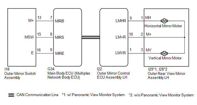
NOTICE:
- The power mirror control system (w/ Memory) uses the CAN communication system. Inspect the communication functions by following How to Proceed with Troubleshooting. Troubleshoot the power mirror control system (w/ Memory) after confirming that the communication systems are functioning properly.
Click here

- Before replacing the main body ECU (multiplex network body ECU), refer to Registration.
Click here
PROCEDURE
READ VALUE USING TECHSTREAM
(a) Connect the Techstream to the DLC3.
(b) Turn the power switch on (IG).
(c) Turn the Techstream on.
(d) Enter the following menus: Body Electrical / Main Body / Data List.
(e) Read the Data List according to the display on the Techstream.
Body Electrical > Main Body > Data ListTester Display | Measurement Item | Range | Normal Condition | Diagnostic Note |
|---|---|---|---|---|
Mirror Selection SW (R) |
Mirror select switch signal for RH mirror |
OFF or ON |
OFF: Mirror select switch off ON: Mirror select switch R switch on |
- |
Mirror Selection SW (L) |
Mirror select switch signal for LH mirror |
OFF or ON |
OFF: Mirror select switch off ON: Mirror select switch L switch on |
- |
Mirror Position SW (R) |
Mirror adjust switch signal (Right) |
OFF or ON |
OFF: Mirror adjust switch not pushed right ON: Mirror adjust switch pushed right |
Check with the mirror select switch L or R selected |
Mirror Position SW (L) |
Mirror adjust switch signal (Left) |
OFF or ON |
OFF: Mirror adjust switch not pushed left ON: Mirror adjust switch pushed left |
Check with the mirror select switch L or R selected |
Mirror Position SW (Up) |
Mirror adjust switch signal (Up) |
OFF or ON |
OFF: Mirror adjust switch not pushed up ON: Mirror adjust switch pushed up |
Check with the mirror select switch L or R selected |
Mirror Position SW (Dwn) |
Mirror adjust switch signal (Down) |
OFF or ON |
OFF: Mirror adjust switch not pushed down ON: Mirror adjust switch pushed down |
Check with the mirror select switch L or R selected |
Tester Display |
|---|
Mirror Selection SW (R) |
Mirror Selection SW (L) |
Mirror Position SW (R) |
Mirror Position SW (L) |
Mirror Position SW (Up) |
Mirror Position SW (Dwn) |
OK:
On the Techstream screen, ON or OFF is displayed accordingly.
| NG |  |
GO TO STEP 4 |
|

INSPECT OUTER REAR VIEW MIRROR ASSEMBLY LH (MIRROR SURFACE)
(a) Remove the outer rear view mirror assembly LH.
Click here
(b) Inspect the outer rear view mirror assembly LH (mirror surface).
Click here
| NG | |
REPLACE OUTER REAR VIEW MIRROR ASSEMBLY LH |
|
CHECK HARNESS AND CONNECTOR (OUTER REAR VIEW MIRROR ASSEMBLY LH - OUTER MIRROR CONTROL ECU ASSEMBLY LH)
(a) Disconnect the I29*1 or I28*2 outer rear view mirror assembly LH.
- *1: w/ Panoramic View Monitor System
- *2: w/o Panoramic View Monitor System
(b) Disconnect the I22 outer mirror control ECU assembly LH.
(c) Measure the resistance according to the value(s) in the table below.
Standard Resistance:
w/ Panoramic View Monitor SystemTester Connection | Condition | Specified Condition |
|---|---|---|
I29-3 (MV) - I22-1 (LMVR) |
Always |
Below 1 Ω |
I29-1 (MH) - I22-9 (LMHR) |
Always |
Below 1 Ω |
I29-2 (M+) - I22-10 (LM+R) |
Always |
Below 1 Ω |
I29-3 (MV) or I22-1 (LMVR) - Body ground |
Always |
10 kΩ or higher |
I29-1 (MH) or I22-9 (LMHR) - Body ground |
Always |
10 kΩ or higher |
I29-2 (M+) or I22-10 (LM+R) - Body ground |
Always |
10 kΩ or higher |
Tester Connection | Condition | Specified Condition |
|---|---|---|
I28-3 (MV) - I22-1 (LMVR) |
Always |
Below 1 Ω |
I28-1 (MH) - I22-9 (LMHR) |
Always |
Below 1 Ω |
I28-2 (M+) - I22-10 (LM+R) |
Always |
Below 1 Ω |
I28-3 (MV) or I22-1 (LMVR) - Body ground |
Always |
10 kΩ or higher |
I28-1 (MH) or I22-9 (LMHR) - Body ground |
Always |
10 kΩ or higher |
I28-2 (M+) or I22-10 (LM+R) - Body ground |
Always |
10 kΩ or higher |
| OK | |
REPLACE OUTER MIRROR CONTROL ECU ASSEMBLY LH |
| NG | |
REPAIR OR REPLACE HARNESS OR CONNECTOR |
INSPECT OUTER MIRROR SWITCH ASSEMBLY
(a) Remove the outer mirror switch assembly.
Click here
(b) Inspect the outer mirror switch assembly.
Click here
| NG | |
REPLACE OUTER MIRROR SWITCH ASSEMBLY |
|
CHECK HARNESS AND CONNECTOR (OUTER MIRROR SWITCH ASSEMBLY - MAIN BODY ECU (MULTIPLEX NETWORK BODY ECU))
(a) Disconnect the I18 outer mirror switch assembly.
(b) Disconnect the G34 main body ECU (multiplex network body ECU).
(c) Measure the resistance according to the value(s) in the table below.
Standard Resistance:
Tester Connection | Condition | Specified Condition |
|---|---|---|
I18-16 (E) - G34-9 (MIRE) |
Always |
Below 1 Ω |
I18-13 (M+) - G34-7 (MIRB) |
Always |
Below 1 Ω |
I18-15 (MSW) - G34-8 (MIRS) |
Always |
Below 1 Ω |
I18-16 (E) or G34-9 (MIRE) - Body ground |
Always |
10 kΩ or higher |
I18-13 (M+) or G34-7 (MIRB) - Body ground |
Always |
10 kΩ or higher |
I18-15 (MSW) or G34-8 (MIRS) - Body ground |
Always |
10 kΩ or higher |
| OK | |
REPLACE MAIN BODY ECU (MULTIPLEX NETWORK BODY ECU) |
| NG | |
REPAIR OR REPLACE HARNESS OR CONNECTOR |
Dtc Check / Clear
DTC CHECK / CLEAR
CHECK DTC
(a) Connect the Techstream to the DLC3.
(b) Turn the power switch on (IG).
(c) Turn the Techstream on.
(d) Enter the following menus: Body Electrical / Mirror L or Mirror R / Trouble Codes.
Body Electrical > Mirror L > Trouble Codes Body Electrical > Mirror R > Trouble Codes(e) Check the details of the DTCs.
Click here 
CLEAR DTC
(a) Connect the Techstream to the DLC3.
(b) Turn the power switch on (IG).
(c) Turn the Techstream on.
(d) Enter the following menus: Body Electrical / Mirror L or Mirror R / Trouble Codes.
Body Electrical > Mirror L > Clear DTCs Body Electrical > Mirror R > Clear DTCs(e) Clear the DTCs.
Front Passenger Side Power Mirror cannot be Adjusted with Power Mirror Switch
DESCRIPTION
The outer mirror switch assembly sends the mirror adjust switch signals to the main body ECU (multiplex network body ECU). The main body ECU (multiplex network body ECU) then sends the received mirror adjust switch signals to the outer mirror control ECU assembly RH via CAN communication. On receiving the signal, the outer mirror control ECU assembly RH operates the vertical and horizontal mirror motors, which are built into the outer rear view mirror assembly RH, to adjust the mirror surface position.
WIRING DIAGRAM
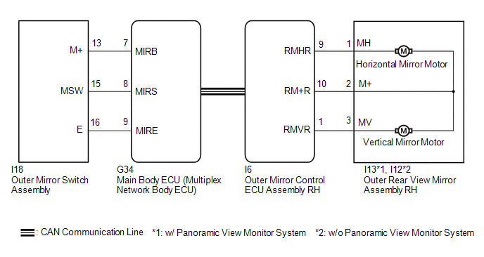
NOTICE:
- The power mirror control system (w/ Memory) uses the CAN communication system. Inspect the communication functions by following How to Proceed with Troubleshooting. Troubleshoot the power mirror control system (w/ Memory) after confirming that the communication systems are functioning properly.
Click here

- Before replacing the main body ECU (multiplex network body ECU), refer to Registration.
Click here
PROCEDURE
READ VALUE USING TECHSTREAM
(a) Connect the Techstream to the DLC3.
(b) Turn the power switch on (IG).
(c) Turn the Techstream on.
(d) Enter the following menus: Body Electrical / Main Body / Data List.
(e) Read the Data List according to the display on the Techstream.
Body Electrical > Main Body > Data ListTester Display | Measurement Item | Range | Normal Condition | Diagnostic Note |
|---|---|---|---|---|
Mirror Selection SW (R) |
Mirror select switch signal for RH mirror |
OFF or ON |
OFF: Mirror select switch off ON: Mirror select switch R switch on |
- |
Mirror Selection SW (L) |
Mirror select switch signal for LH mirror |
OFF or ON |
OFF: Mirror select switch off ON: Mirror select switch L switch on |
- |
Mirror Position SW (R) |
Mirror adjust switch signal (Right) |
OFF or ON |
OFF: Mirror adjust switch not pushed right ON: Mirror adjust switch pushed right |
Check with the mirror select switch L or R selected |
Mirror Position SW (L) |
Mirror adjust switch signal (Left) |
OFF or ON |
OFF: Mirror adjust switch not pushed left ON: Mirror adjust switch pushed left |
Check with the mirror select switch L or R selected |
Mirror Position SW (Up) |
Mirror adjust switch signal (Up) |
OFF or ON |
OFF: Mirror adjust switch not pushed up ON: Mirror adjust switch pushed up |
Check with the mirror select switch L or R selected |
Mirror Position SW (Dwn) |
Mirror adjust switch signal (Down) |
OFF or ON |
OFF: Mirror adjust switch not pushed down ON: Mirror adjust switch pushed down |
Check with the mirror select switch L or R selected |
Tester Display |
|---|
Mirror Selection SW (R) |
Mirror Selection SW (L) |
Mirror Position SW (R) |
Mirror Position SW (L) |
Mirror Position SW (Up) |
Mirror Position SW (Dwn) |
OK:
On the Techstream screen, ON or OFF is displayed accordingly.
| NG |  |
GO TO STEP 4 |
|

INSPECT OUTER REAR VIEW MIRROR ASSEMBLY RH (MIRROR SURFACE)
(a) Remove the outer rear view mirror assembly RH.
Click here
(b) Inspect the outer rear view mirror assembly RH (mirror surface).
Click here
| NG | |
REPLACE OUTER REAR VIEW MIRROR ASSEMBLY RH |
|
CHECK HARNESS AND CONNECTOR (OUTER REAR VIEW MIRROR ASSEMBLY RH - OUTER MIRROR CONTROL ECU ASSEMBLY RH)
(a) Disconnect the I13*1 or I12*2 outer rear view mirror assembly RH.
- *1: w/ Panoramic View Monitor System
- *2: w/o Panoramic View Monitor System
(b) Disconnect the I6 outer mirror control ECU assembly RH.
(c) Measure the resistance according to the value(s) in the table below.
Standard Resistance:
w/ Panoramic View Monitor SystemTester Connection | Condition | Specified Condition |
|---|---|---|
I13-3 (MV) - I6-1 (RMVR) |
Always |
Below 1 Ω |
I13-1 (MH) - I6-9 (RMHR) |
Always |
Below 1 Ω |
I13-2 (M+) - I6-10 (RM+R) |
Always |
Below 1 Ω |
I13-3 (MV) or I6-1 (RMVR) - Body ground |
Always |
10 kΩ or higher |
I13-1 (MH) or I6-9 (RMHR) - Body ground |
Always |
10 kΩ or higher |
I13-2 (M+) or I6-10 (RM+R) - Body ground |
Always |
10 kΩ or higher |
Tester Connection | Condition | Specified Condition |
|---|---|---|
I12-3 (MV) - I6-1 (RMVR) |
Always |
Below 1 Ω |
I12-1 (MH) - I6-9 (RMHR) |
Always |
Below 1 Ω |
I12-2 (M+) - I6-10 (RM+R) |
Always |
Below 1 Ω |
I12-3 (MV) or I6-1 (RMVR) - Body ground |
Always |
10 kΩ or higher |
I12-1 (MH) or I6-9 (RMHR) - Body ground |
Always |
10 kΩ or higher |
I12-2 (M+) or I6-10 (RM+R) - Body ground |
Always |
10 kΩ or higher |
| OK | |
REPLACE OUTER MIRROR CONTROL ECU ASSEMBLY RH |
| NG | |
REPAIR OR REPLACE HARNESS OR CONNECTOR |
INSPECT OUTER MIRROR SWITCH ASSEMBLY
(a) Remove the outer mirror switch assembly.
Click here
(b) Inspect the outer mirror switch assembly.
Click here
| NG | |
REPLACE OUTER MIRROR SWITCH ASSEMBLY |
|
CHECK HARNESS AND CONNECTOR (OUTER MIRROR SWITCH ASSEMBLY - MAIN BODY ECU (MULTIPLEX NETWORK BODY ECU))
(a) Disconnect the I18 outer mirror switch assembly.
(b) Disconnect the G34 main body ECU (multiplex network body ECU).
(c) Measure the resistance according to the value(s) in the table below.
Standard Resistance:
Tester Connection | Condition | Specified Condition |
|---|---|---|
I18-16 (E) - G34-9 (MIRE) |
Always |
Below 1 Ω |
I18-13 (M+) - G34-7 (MIRB) |
Always |
Below 1 Ω |
I18-15 (MSW) - G34-8 (MIRS) |
Always |
Below 1 Ω |
I18-16 (E) or G34-9 (MIRE) - Body ground |
Always |
10 kΩ or higher |
I18-13 (M+) or G34-7 (MIRB) - Body ground |
Always |
10 kΩ or higher |
I18-15 (MSW) or G34-8 (MIRS) - Body ground |
Always |
10 kΩ or higher |
| OK | |
REPLACE MAIN BODY ECU (MULTIPLEX NETWORK BODY ECU) |
| NG | |
REPAIR OR REPLACE HARNESS OR CONNECTOR |
How To Proceed With Troubleshooting
HINT:
- Use the following procedure to troubleshoot the power mirror control system (w/ Memory).
- *: Use the Techstream.
PROCEDURE
VEHICLE BROUGHT TO WORKSHOP
|

CUSTOMER PROBLEM ANALYSIS
HINT:
- In troubleshooting, confirm that the problem symptoms have been accurately identified. Preconceptions should be discarded in order to make an accurate judgment. To clearly understand what the problem symptoms are, it is extremely important to ask the customer about the problem and the conditions at the time the malfunction occurred.
- Gather as much information as possible for reference. Past problems that seem unrelated may also help in some cases.
- The following 5 items are important points for problem analysis:
What
Vehicle model, system name
When
Date, time, occurrence frequency
Where
Road conditions
Under what conditions?
Driving conditions, weather conditions
How did it happen?
Problem symptoms
|
PRE-CHECK
(a) Measure the auxiliary battery voltage with the power switch off.
Standard Voltage:
11 to 14 V
If the voltage is below 11 V, recharge or replace the auxiliary battery before proceeding to the next step.
(b) Check the fuses and relays.
(c) Check the connector connections and terminals to make sure that there are no abnormalities such as loose connections, deformation, etc.
|
CHECK COMMUNICATION FUNCTION OF CAN COMMUNICATION SYSTEM*
(a) Using the Techstream, check for CAN communication system DTCs.
Click here 
Result | Proceed to |
|---|---|
CAN DTCs are not output |
A |
CAN DTCs are output |
B |
| B |  |
GO TO CAN COMMUNICATION SYSTEM |
|
PROBLEM SYMPTOMS TABLE
(a) Refer to Problem Symptoms Table.
Click here
Result | Proceed to |
|---|---|
Fault is not listed in Problem Symptoms Table |
A |
Fault is listed in Problem Symptoms Table |
B |
| B | |
GO TO STEP 7 |
|
OVERALL ANALYSIS AND TROUBLESHOOTING*
(a) Operation Check
Click here
(b) Terminals of ECU
Click here
(c) Data List / Active Test
Click here
(d) Inspection
|
REPAIR OR REPLACE
|
CONFIRMATION TEST
| NEXT | |
END |
Mirror Heater does not Operate with Rear Defogger Switch
DESCRIPTION
When the mirror heater switch (rear window defogger switch) is operated, the mirror heater signal is sent to the air conditioning amplifier assembly and then to each outer mirror control ECU assembly via CAN communication. Based on this signal, the outer mirror control ECU assemblies operate the mirror heaters.
WIRING DIAGRAM
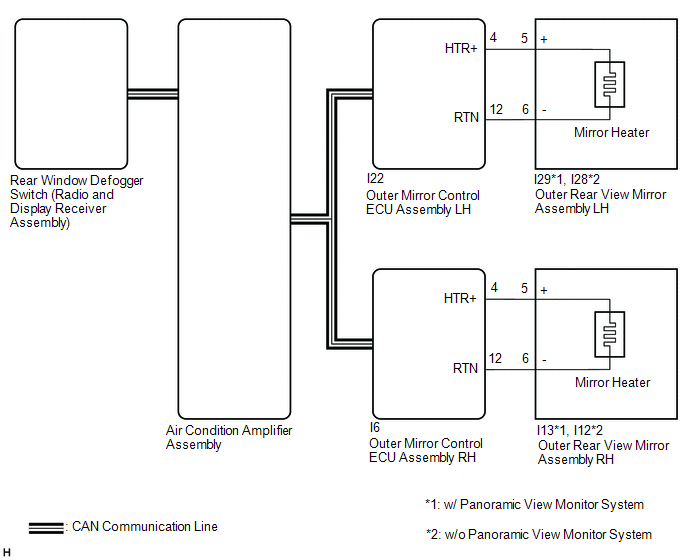
NOTICE:
- The power mirror control system (w/ Memory) uses the CAN communication system. Inspect the communication functions by following How to Proceed with Troubleshooting. Troubleshoot the power mirror control system (w/ Memory) after confirming that the communication systems are functioning properly.
Click here

- If the auxiliary battery voltage is low, the mirror heater function may not operate.
PROCEDURE
CHECK WINDOW DEFOGGER SYSTEM
(a) Check window defogger system operation.
Click here
OK:
Window defogger system is normal.
| NG |  |
GO TO WINDOW DEFOGGER SYSTEM |
|

PERFORM ACTIVE TEST USING TECHSTREAM
(a) Connect the Techstream to the DLC3.
(b) Turn the power switch on (IG).
(c) Turn the Techstream on.
(d) Enter the following menus: Body Electrical / Mirror L or Mirror R / Active Test.
(e) Perform an Active Test according to the display on the Techstream.
Body Electrical > Mirror L > Active TestTester Display | Measurement Item | Control Range | Diagnostic Note |
|---|---|---|---|
Mirror Heater |
Mirror heater operation |
OFF or ON |
|
Mirror Heater
Body Electrical > Mirror R > Active TestTester Display | Measurement Item | Control Range | Diagnostic Note |
|---|---|---|---|
Mirror Heater |
Mirror heater operation |
OFF or ON |
|
Mirror Heater
Result | Proceed to |
|---|---|
Mirror heater operation on both mirrors is normal |
A |
Mirror heater operation on driver door mirror is not normal |
B |
Mirror heater operation on front passenger door mirror is not normal |
C |
| A | |
REPLACE AIR CONDITIONING AMPLIFIER ASSEMBLY |
| C | |
GO TO STEP 6 |
|
CHECK HARNESS AND CONNECTOR (OUTER MIRROR CONTROL ECU ASSEMBLY LH - OUTER REAR VIEW MIRROR ASSEMBLY LH)
(a) Disconnect the I22 outer mirror control ECU assembly LH connector.
(b) Disconnect the I29*1 or I28*2 outer rear view mirror assembly LH connector.
- *1: w/ Panoramic View Monitor System
- *2: w/o Panoramic View Monitor System
(c) Measure the resistance according to the value(s) in the table below.
Standard Resistance:
w/ Panoramic View Monitor SystemTester Connection | Condition | Specified Condition |
|---|---|---|
I22-4 (HTR+) - I29-5 (+) |
Always |
Below 1 Ω |
I22-12 (RTN) - I29-6 (-) |
Always |
Below 1 Ω |
I22-4 (HTR+) or I29-5 (+) - Body ground |
Always |
10 kΩ or higher |
I22-12 (RTN) or I29-6 (-) - Body ground |
Always |
10 kΩ or higher |
Tester Connection | Condition | Specified Condition |
|---|---|---|
I22-4 (HTR+) - I28-5 (+) |
Always |
Below 1 Ω |
I22-12 (RTN) - I28-6 (-) |
Always |
Below 1 Ω |
I22-4 (HTR+) or I28-5 (+) - Body ground |
Always |
10 kΩ or higher |
I22-12 (RTN) or I28-6 (-) - Body ground |
Always |
10 kΩ or higher |
| NG | |
REPAIR OR REPLACE HARNESS OR CONNECTOR |
|
INSPECT OUTER MIRROR LH
(a) Remove the outer mirror LH.
Click here
(b) Inspect the outer mirror LH.
Click here
| NG | |
REPLACE OUTER MIRROR LH |
|
INSPECT OUTER REAR VIEW MIRROR ASSEMBLY LH (MIRROR HEATER)
(a) Remove the outer rear view mirror assembly LH.
Click here
(b) Inspect the outer rear view mirror assembly LH (mirror heater).
Click here
| OK | |
REPLACE OUTER MIRROR CONTROL ECU ASSEMBLY LH |
| NG | |
REPLACE OUTER REAR VIEW MIRROR ASSEMBLY LH |
CHECK HARNESS AND CONNECTOR (OUTER MIRROR CONTROL ECU ASSEMBLY RH - OUTER REAR VIEW MIRROR ASSEMBLY RH)
(a) Disconnect the I6 outer mirror control ECU assembly RH connector.
(b) Disconnect the I13*1 or I12*2 outer rear view mirror assembly RH connector.
- *1: w/ Panoramic View Monitor System
- *2: w/o Panoramic View Monitor System
(c) Measure the resistance according to the value(s) in the table below.
Standard Resistance:
w/ Panoramic View Monitor SystemTester Connection | Condition | Specified Condition |
|---|---|---|
I6-4 (HTR+) - I13-5 (+) |
Always |
Below 1 Ω |
I6-12 (RTN) - I13-6 (-) |
Always |
Below 1 Ω |
I6-4 (HTR+) or I13-5 (+) - Body ground |
Always |
10 kΩ or higher |
I6-12 (RTN) or I13-6 (-) - Body ground |
Always |
10 kΩ or higher |
Tester Connection | Condition | Specified Condition |
|---|---|---|
I6-4 (HTR+) - I12-5 (+) |
Always |
Below 1 Ω |
I6-12 (RTN) - I12-6 (-) |
Always |
Below 1 Ω |
I6-4 (HTR+) or I12-5 (+) - Body ground |
Always |
10 kΩ or higher |
I6-12 (RTN) or I12-6 (-) - Body ground |
Always |
10 kΩ or higher |
| NG | |
REPAIR OR REPLACE HARNESS OR CONNECTOR |
|
INSPECT OUTER MIRROR RH
(a) Remove the outer mirror RH.
Click here
(b) Inspect the outer mirror RH.
Click here
| NG | |
REPLACE OUTER MIRROR RH |
|
INSPECT OUTER REAR VIEW MIRROR ASSEMBLY RH (MIRROR HEATER)
(a) Remove the outer rear view mirror assembly RH.
Click here
(b) Inspect the outer rear view mirror assembly RH (mirror heater).
Click here
| OK | |
REPLACE OUTER MIRROR CONTROL ECU ASSEMBLY RH |
| NG | |
REPLACE OUTER REAR VIEW MIRROR ASSEMBLY RH |
Operation Check
OPERATION CHECK
CHECK ELECTRICAL REMOTE CONTROL MIRROR FUNCTION
(a) Turn the power switch on (IG).
(b) With the mirror select switch L switch on, check that the outer rear view mirror assembly LH surface moves up, down, left and right normally.
(c) With the mirror select switch R switch on, check that the outer rear view mirror assembly RH surface moves up, down, left and right normally.
CHECK MEMORY AND REACTIVATION FUNCTION
HINT:
The SET, M1 and M2 seat memory switches are shown in the illustration.
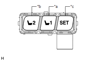
*a |
M1 Switch |
*b |
M2 Switch |
*c |
SET Switch |
(a) Turn the power switch on (IG) and move the shift lever to P.
(b) Check the M1 switch.
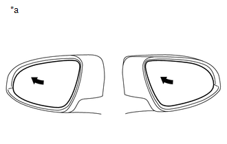
*a |
Turn to Fully Left Position |
(1) Using the outer mirror switch assembly, turn the mirror surface to the fully left position.
(2) Check that the buzzer sounds for 0.5 seconds and the seat and mirror surface position is memorized when the M1 switch is pressed within 3 seconds of the SET switch being pressed.
NOTICE:
- The mirror surface position will also be memorized when the M1 switch is pressed after first pressing and holding the SET switch.
- The mirror surface position will not be memorized when the SET switch and M1 switch are pressed simultaneously.
- The mirror surface position will not be memorized when 2 or more of the memory switches are pressed simultaneously (for example, M1 and M2) after first pressing the SET switch.
(3) Using the outer mirror switch assembly, turn the mirror surface to the fully right position.
(4) Press the M1 switch.
(5) Check that the buzzer sounds for 0.1 seconds and the mirror surface automatically moves to the memorized fully left position.
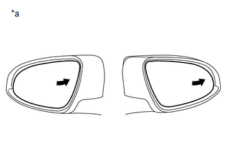
*a |
Turn to Fully Right Position |
(c) Check the M2 switch.
(1) Using the outer mirror switch assembly, turn the mirror surface to the fully right position.
(2) Check that the buzzer sounds for 0.5 seconds and the seat and mirror surface position is memorized when the M2 switch is pressed within 3 seconds of the SET switch being pressed.
NOTICE:
- The mirror surface position will also be memorized when the M2 switch is pressed after first pressing and holding the SET switch.
- The mirror surface position will not be memorized when the SET switch and M2 switch are pressed simultaneously.
- The mirror surface position will not be memorized when 2 or more of the memory switches are pressed simultaneously (for example, M1 and M2) after first pressing the SET switch.
(3) Using the outer mirror switch assembly, turn the mirror surface to the fully left position.
(4) Press the M2 switch.
(5) Check that the buzzer sounds for 0.1 seconds and the mirror surface automatically moves to the memorized fully right position.
CHECK MEMORY CALL FUNCTION
(a) Memory call function check
(1) With an electrical key transmitter sub-assembly recognition code registered, perform a wireless door unlock operation and check that opening the driver door causes the following:
- The buzzer sounds for 0.1 seconds.
- The driver seat and mirror surface positions automatically move to the memorized positions.
HINT:
- The registered electrical key transmitter sub-assembly recognition code is recalled automatically.
- If the memory call function is not operated, the buzzer will not sound.
(b) With the power switch on (IG) and the driver door closed, press and hold the M1 or M2 switch while carrying the electrical key transmitter sub-assembly. The main body ECU (multiplex network body ECU) will enter electrical key transmitter sub-assembly recognition code registration mode to allow a key to be linked to mirror surface memory position.
HINT:
If the seat memory switch is released before entering registration mode, the main body ECU (multiplex network body ECU) will not enter registration mode.
(c) When the manual door lock switch is pressed, check that the buzzer sounds once (0.5 seconds).
(d) With the power switch on (IG) and the driver door closed, press and hold the SET switch while carrying the electrical key transmitter sub-assembly. The main body ECU (multiplex network body ECU) will enter electrical key transmitter sub-assembly recognition code deletion mode.
HINT:
If the seat memory switch is released before entering deletion mode, the main body ECU (multiplex network body ECU) will not enter deletion mode.
(e) When the manual door lock switch is pressed, check that the buzzer sounds twice (0.1 seconds each time).
CHECK MEMORY CALL EMERGENCY STOP FUNCTION
(a) While a memory call function is operating, check that any one of the following actions will stop the memory call operation: 1) pressing the SET, M1 or M2 switch, 2) moving the shift lever to R, 3) moving the mirror surface manually, or 4) moving the mirror surface to the uppermost, lowermost, leftmost or rightmost position.
CHECK MIRROR HEATER FUNCTION
(a) Turn the power switch on (IG).
(b) Check that pressing the mirror heater switch (rear window defogger switch) illuminates the indicator and warms the mirror surfaces.
(c) Check that after approximately 15 minutes, the indicator light turns off and the mirror heaters deactivate.
CHECK AUTOMATIC GLARE-RESISTANT EC MIRROR FUNCTION
(a) Check that the automatic glare-resistant EC mirror function of the outer rear view mirror assemblies operates when the automatic glare-resistant function of the inner rear view mirror assembly operaties.
Parts Location
PARTS LOCATION
ILLUSTRATION
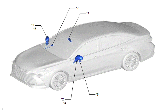
*1 |
INNER REAR VIEW MIRROR ASSEMBLY |
*2 |
OUTER REAR VIEW MIRROR ASSEMBLY LH |
*3 |
OUTER REAR VIEW MIRROR ASSEMBLY RH |
*4 |
OUTER MIRROR LH |
*5 |
OUTER MIRROR RH |
*6 |
OUTER MIRROR CONTROL ECU ASSEMBLY LH |
*7 |
OUTER MIRROR CONTROL ECU ASSEMBLY RH |
- |
- |
ILLUSTRATION
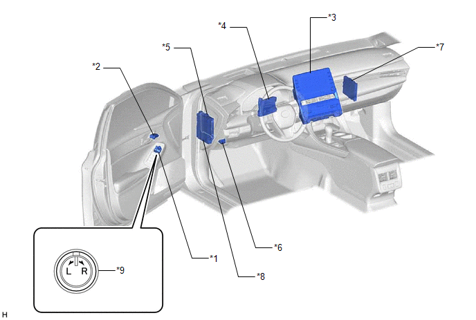
*1 |
OUTER MIRROR SWITCH ASSEMBLY |
*2 |
SEAT MEMORY SWITCH |
*3 |
REAR WINDOW DEFOGGER SWITCH (RADIO AND DISPLAY RECEIVER ASSEMBLY) |
*4 |
AIR CONDITIONING AMPLIFIER ASSEMBLY |
*5 |
MAIN BODY ECU (MULTIPLEX NETWORK BODY ECU) |
*6 |
DLC3 |
*7 |
CERTIFICATION ECU (SMART KEY ECU ASSEMBLY) |
*8 |
INSTRUMENT PANEL JUNCTION BLOCK ASSEMBLY - DOOR F/R FUSE - DOOR F/L FUSE - ECU-IG1 NO. 4 FUSE - ECU-DCC NO. 2 FUSE |
*9 |
MIRROR SELECT AND SURFACE ADJUST SWITCH |
- |
- |
Power Mirror cannot be Adjusted with Power Mirror Switch
DESCRIPTION
The outer mirror switch assembly sends the mirror adjust switch signals to the main body ECU (multiplex network body ECU). The main body ECU (multiplex network body ECU) then sends the received mirror adjust switch signals to each outer mirror control ECU assembly via CAN communication. Based on this signal, each outer mirror control ECU assembly operates the vertical and horizontal mirror motors to adjust the mirror surface position.
WIRING DIAGRAM
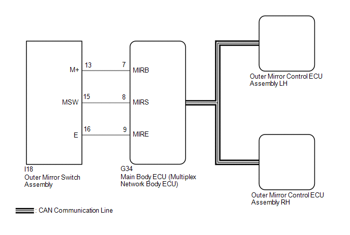
NOTICE:
- The power mirror control system (w/ Memory) uses the CAN communication system. Inspect the communication functions by following How to Proceed with Troubleshooting. Troubleshoot the power mirror control system (w/ Memory) after confirming that the communication systems are functioning properly.
Click here

- Before replacing the main body ECU (multiplex network body ECU), refer to Registration.
Click here
PROCEDURE
READ VALUE USING TECHSTREAM
(a) Connect the Techstream to the DLC3.
(b) Turn the power switch on (IG).
(c) Turn the Techstream on.
(d) Enter the following menus: Body Electrical / Main Body / Data List.
(e) Read the Data List according to the display on the Techstream.
Body Electrical > Main Body > Data ListTester Display | Measurement Item | Range | Normal Condition | Diagnostic Note |
|---|---|---|---|---|
Mirror Selection SW (R) |
Mirror select switch signal for RH mirror |
OFF or ON |
OFF: Mirror select switch off ON: Mirror select switch R switch on |
- |
Mirror Selection SW (L) |
Mirror select switch signal for LH mirror |
OFF or ON |
OFF: Mirror select switch off ON: Mirror select switch L switch on |
- |
Mirror Position SW (R) |
Mirror adjust switch signal (Right) |
OFF or ON |
OFF: Mirror adjust switch not pushed right ON: Mirror adjust switch pushed right |
Check with the mirror select switch L or R selected |
Mirror Position SW (L) |
Mirror adjust switch signal (Left) |
OFF or ON |
OFF: Mirror adjust switch not pushed left ON: Mirror adjust switch pushed left |
Check with the mirror select switch L or R selected |
Mirror Position SW (Up) |
Mirror adjust switch signal (Up) |
OFF or ON |
OFF: Mirror adjust switch not pushed up ON: Mirror adjust switch pushed up |
Check with the mirror select switch L or R selected |
Mirror Position SW (Dwn) |
Mirror adjust switch signal (Down) |
OFF or ON |
OFF: Mirror adjust switch not pushed down ON: Mirror adjust switch pushed down |
Check with the mirror select switch L or R selected |
Tester Display |
|---|
Mirror Selection SW (R) |
Mirror Selection SW (L) |
Mirror Position SW (R) |
Mirror Position SW (L) |
Mirror Position SW (Up) |
Mirror Position SW (Dwn) |
OK:
On the Techstream screen, ON or OFF is displayed accordingly.
| OK |  |
REPLACE MAIN BODY ECU (MULTIPLEX NETWORK BODY ECU) |
|

INSPECT OUTER MIRROR SWITCH ASSEMBLY
(a) Remove the outer mirror switch assembly.
Click here
(b) Inspect the outer mirror switch assembly.
Click here
| NG | |
REPLACE OUTER MIRROR SWITCH ASSEMBLY |
|
CHECK HARNESS AND CONNECTOR (OUTER MIRROR SWITCH ASSEMBLY - MAIN BODY ECU (MULTIPLEX NETWORK BODY ECU))
(a) Disconnect the I18 outer mirror switch assembly.
(b) Disconnect the G34 main body ECU (multiplex network body ECU).
(c) Measure the resistance according to the value(s) in the table below.
Standard Resistance:
Tester Connection | Condition | Specified Condition |
|---|---|---|
I18-16 (E) - G34-9 (MIRE) |
Always |
Below 1 Ω |
I18-13 (M+) - G34-7 (MIRB) |
Always |
Below 1 Ω |
I18-15 (MSW) - G34-8 (MIRS) |
Always |
Below 1 Ω |
I18-16 (E) or G34-9 (MIRE) - Body ground |
Always |
10 kΩ or higher |
I18-13 (M+) or G34-7 (MIRB) - Body ground |
Always |
10 kΩ or higher |
I18-15 (MSW) or G34-8 (MIRS) - Body ground |
Always |
10 kΩ or higher |
| OK | |
REPLACE MAIN BODY ECU (MULTIPLEX NETWORK BODY ECU) |
| NG | |
REPAIR OR REPLACE HARNESS OR CONNECTOR |
Power Mirror Surface Position is not Memorized
DESCRIPTION
If any of the M1 or M2 seat memory switch is pressed, the outer mirror control ECU assembly LH detects the switch operation and sends the seat memory switch signal to the main body ECU (multiplex network body ECU) via CAN communication. On receiving the seat memory switch signal, the main body ECU (multiplex network body ECU) sends the memory request signal to each outer mirror control ECU assembly via CAN communication. When receiving this signal, each outer mirror control ECU assembly stores the mirror surface position based on information from the mirror position sensor, which is built into the outer rear view mirror assembly.
WIRING DIAGRAM
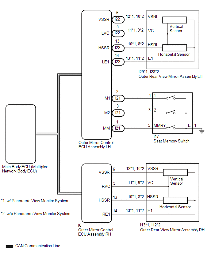
NOTICE:
- The power mirror control system (w/ Memory) uses the CAN communication system. First, confirm that there is no malfunction in the CAN communication system. Refer to the How to Proceed with Troubleshooting procedure.
Click here

- Before replacing the main body ECU (multiplex network body ECU), refer to Registration.
Click here
- The mirror surface position will not be memorized if the power switch is not on (IG).
- The mirror surface position will not be stored if the seat memory SET switch and 2 or more seat memory switches are pressed simultaneously.
- If the operation fails, the mirror surface position will not be memorized until the seat memory SET switch is released and the operation is attempted again.
- The mirror surface position will not be memorized when the mirror is operated manually.
HINT:
Each outer rear view mirror assembly has a built-in mirror vertical position sensor and mirror horizontal position sensor.
PROCEDURE
READ VALUE USING TECHSTREAM
(a) Connect the Techstream to the DLC3.
(b) Turn the power switch on (IG).
(c) Turn the Techstream on.
(d) Enter the following menus: Body Electrical / Mirror L or Mirror R / Data List.
(e) Read the Data List according to the display on the Techstream.
Body Electrical > Mirror L > Data ListTester Display | Measurement Item | Range | Normal Condition | Diagnostic Note |
|---|---|---|---|---|
Seat Memory Switch1 |
Seat memory switch M1 switch signal |
OFF or ON |
OFF: Seat memory switch M1 switch off ON: Seat memory switch M1 switch on |
- |
Seat Memory Switch2 |
Seat memory switch M2 switch signal |
OFF or ON |
OFF: Seat memory switch M2 switch off ON: Seat memory switch M2 switch on |
- |
Seat Memory Set SW |
Seat memory switch SET switch signal |
OFF or ON |
OFF: Seat memory switch SET switch off ON: Seat memory switch SET switch on |
- |
Tester Display |
|---|
Seat Memory Switch1 |
Seat Memory Switch2 |
Seat Memory Set SW |
Tester Display | Measurement Item | Range | Normal Condition | Diagnostic Note |
|---|---|---|---|---|
Seat Memory Switch1 |
Seat memory switch M1 switch signal |
OFF or ON |
OFF: Seat memory switch M1 switch off ON: Seat memory switch M1 switch on |
- |
Seat Memory Switch2 |
Seat memory switch M2 switch signal |
OFF or ON |
OFF: Seat memory switch M2 switch off ON: Seat memory switch M2 switch on |
- |
Seat Memory Set SW |
Seat memory switch SET switch signal |
OFF or ON |
OFF: Seat memory switch SET switch off ON: Seat memory switch SET switch on |
- |
Tester Display |
|---|
Seat Memory Switch1 |
Seat Memory Switch2 |
Seat Memory Set SW |
OK:
On the Techstream screen, ON or OFF is displayed accordingly.
| NG |  |
GO TO STEP 8 |
|

CHECK SEAT MEMORY SWITCH (SEAT POSITION MEMORY FUNCTION)
(a) When any seat memory switch (M1 or M2) is pressed, check that the driver seat moves to the memorized position.
Click here
OK:
The driver seat moves to the memorized position.
| NG | |
GO TO FRONT POWER SEAT CONTROL SYSTEM (Power Seat does not Return to Memorized Position) |
|
CHECK MEMORY AND REACTIVATION FUNCTION
(a) Turn the power switch on (IG). |
|
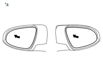
(b) Using the outer mirror switch assembly, turn the mirror surface to the fully left position.
(c) Press the M1 switch while the SET switch is being pressed.
(d) Check that the buzzer sounds for 0.5 seconds and the mirror surface position is memorized.
(e) Using the outer mirror switch assembly, turn the mirror surface to the fully right position.
(f) Press the M1 switch.
(g) Check that the buzzer sounds for 0.1 seconds and the outer mirror automatically moves to the memorized fully left position.
Result | Proceed to |
|---|---|
Memory and reactivation functions on both mirrors are not normal |
A |
Memory and reactivation functions on driver door mirror are not normal |
B |
Memory and reactivation functions on front passenger door mirror are not normal |
C |
| A | |
REPLACE MAIN BODY ECU (MULTIPLEX NETWORK BODY ECU) |
| C | |
GO TO STEP 6 |
|
REPLACE OUTER REAR VIEW MIRROR ASSEMBLY LH
(a) Temporarily replace the outer rear view mirror assembly LH with a new or known good one.
Click here
|
CHECK MEMORY AND REACTIVATION FUNCTION
(a) Turn the power switch on (IG). |
|
(b) Using the outer mirror switch assembly, turn the mirror surface to the fully left position.
(c) Press the M1 switch while the SET switch is being pressed.
(d) Check that the buzzer sounds for 0.5 seconds and the mirror surface position is memorized.
(e) Using the outer mirror switch assembly, turn the mirror surface to the fully right position.
(f) Press the M1 switch.
(g) Check that the buzzer sounds for 0.1 seconds and the outer mirror automatically moves to the memorized fully left position.
| OK | |
END (OUTER REAR VIEW MIRROR ASSEMBLY LH WAS DEFECTIVE) |
| NG | |
REPLACE OUTER MIRROR CONTROL ECU ASSEMBLY LH |
REPLACE OUTER REAR VIEW MIRROR ASSEMBLY RH
(a) Temporarily replace the outer rear view mirror assembly RH with a new or known good one.
Click here
|
CHECK MEMORY AND REACTIVATION FUNCTION
(a) Turn the power switch on (IG). |
|
(b) Using the outer mirror switch assembly, turn the mirror surface to the fully left position.
(c) Press the M1 switch while the SET switch is being pressed.
(d) Check that the buzzer sounds for 0.5 seconds and the mirror surface position is memorized.
(e) Using the outer mirror switch assembly, turn the mirror surface to the fully right position.
(f) Press the M1 switch.
(g) Check that the buzzer sounds for 0.1 seconds and the outer mirror automatically moves to the memorized fully left position.
| OK | |
END (OUTER REAR VIEW MIRROR ASSEMBLY RH WAS DEFECTIVE) |
| NG | |
REPLACE OUTER MIRROR CONTROL ECU ASSEMBLY RH |
INSPECT SEAT MEMORY SWITCH
(a) Remove the seat memory switch.
Click here
(b) Inspect the seat memory switch.
Click here
| NG | |
REPLACE SEAT MEMORY SWITCH |
|
CHECK HARNESS AND CONNECTOR (SEAT MEMORY SWITCH - OUTER MIRROR CONTROL ECU ASSEMBLY LH - BODY GROUND)
(a) Disconnect the I21 outer mirror control ECU assembly LH connector.
(b) Disconnect the I17 seat memory switch connector.
(c) Measure the resistance according to the value(s) in the table below.
Standard Resistance:
Tester Connection | Condition | Specified Condition |
|---|---|---|
I21-1 (MM) - I17-5 (MMRY) |
Always |
Below 1 Ω |
I21-1 (MM) or I17-5 (MMRY) - Body ground |
Always |
10 kΩ or higher |
I21-2 (M1) - I17-4 (1) |
Always |
Below 1 Ω |
I21-2 (M1) or I17-4 (1) - Body ground |
Always |
10 kΩ or higher |
I21-3 (M2) - I17-3 (2) |
Always |
Below 1 Ω |
I21-3 (M2) or I17-3 (2) - Body ground |
Always |
10 kΩ or higher |
I17-1 (E) - Body ground |
Always |
Below 1 Ω |
| OK | |
REPLACE OUTER MIRROR CONTROL ECU ASSEMBLY LH |
| NG | |
REPAIR OR REPLACE HARNESS OR CONNECTOR |
Power Mirrors do not Return to Memorized Position
DESCRIPTION
If any of the M1 or M2 seat memory switch is pressed, the outer mirror control ECU assembly LH detects the switch operation and sends the seat memory switch signal to the main body ECU (multiplex network body ECU) via CAN communication. The main body ECU (multiplex network body ECU) sends the reproduction signal to each outer mirror control ECU assembly via CAN communication. When receiving the reproduction signal, each outer mirror control ECU assembly operates the vertical and horizontal mirror motors, which are built into the outer rear view mirror assembly, to adjust the mirror surface to the stored position.
WIRING DIAGRAM
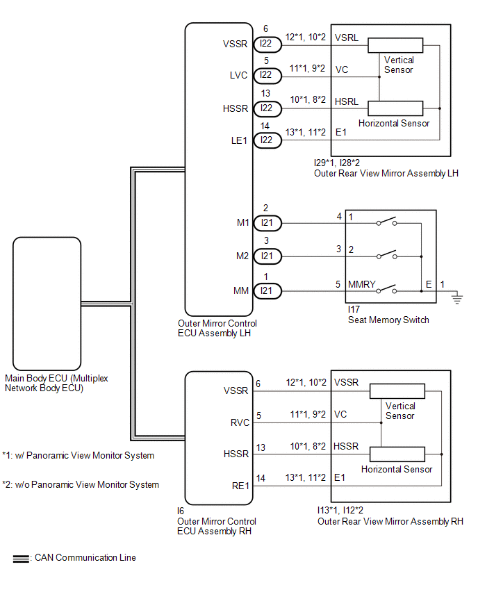
NOTICE:
- The power mirror control system (w/ Memory) uses the CAN communication system. First, confirm that there is no malfunction in the CAN communication system. Refer to the How to Proceed with Troubleshooting procedure.
Click here

- Before replacing the main body ECU (multiplex network body ECU), refer to Registration.
Click here
PROCEDURE
CHECK SEAT MEMORY SWITCH FUNCTION
(a) When any seat memory switch (M1 or M2) is pressed, check that the driver seat moves to the memorized position.
Click here
OK:
Driver seat moves to the memorized position.
| NG |  |
GO TO FRONT POWER SEAT CONTROL SYSTEM (Power Seat does not Return to Memorized Position) |
|

CHECK ELECTRICAL REMOTE CONTROL MIRROR FUNCTION
(a) Check the electrical remote control mirror function.
Click here
OK:
Electrical remote control mirror function is normal.
| NG | |
GO TO OTHER DIAGNOSTIC PROCEDURE (Power Mirror cannot be Adjusted with Power Mirror Switch) |
|
READ VALUE USING TECHSTREAM
(a) Connect the Techstream to the DLC3.
(b) Turn the power switch on (IG).
(c) Turn the Techstream on.
(d) Enter the following menus: Body Electrical / Mirror L or Mirror R / Data List.
(e) Read the Data List according to the display on the Techstream.
Body Electrical > Mirror L > Data ListTester Display | Measurement Item | Range | Normal Condition | Diagnostic Note |
|---|---|---|---|---|
Mirror Memory No.1 |
Mirror position memorized in memory switch M1 |
OFF or ON |
OFF: Not memorized ON: Memorized |
- |
Mirror Memory No.2 |
Mirror position memorized in memory switch M2 |
OFF or ON |
OFF: Not memorized ON: Memorized |
- |
Tester Display |
|---|
Mirror Memory No.1 |
Mirror Memory No.2 |
Tester Display | Measurement Item | Range | Normal Condition | Diagnostic Note |
|---|---|---|---|---|
Mirror Memory No.1 |
Mirror position memorized in memory switch M1 |
OFF or ON |
OFF: Not memorized ON: Memorized |
- |
Mirror Memory No.2 |
Mirror position memorized in memory switch M2 |
OFF or ON |
OFF: Not memorized ON: Memorized |
- |
Tester Display |
|---|
Mirror Memory No.1 |
Mirror Memory No.2 |
OK:
ON (Memorized) appears on the screen.
| NG | |
GO TO OTHER DIAGNOSTIC PROCEDURE (Power Mirror Surface Position is not Memorized) |
|
CHECK MEMORY AND REACTIVATION FUNCTION
(a) Turn the power switch on (IG). |
|
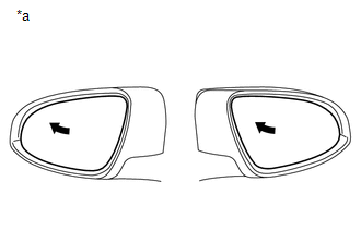
(b) Using the outer mirror switch assembly, turn the mirror surface to the fully left position.
(c) Press the M1 switch while the SET switch is being pressed.
(d) Check that the buzzer sounds for 0.5 seconds and the mirror surface position is memorized.
(e) Using the outer mirror switch assembly, turn the mirror surface to the fully right position.
(f) Press the M1 switch.
(g) Check that the buzzer sounds for 0.1 seconds and the outer mirror automatically moves to the memorized fully left position.
Result | Proceed to |
|---|---|
Memory and reactivation functions on both mirrors are not normal |
A |
Memory and reactivation function on driver door mirror is not normal |
B |
Memory and reactivation function on front passenger door mirror is not normal |
C |
| A | |
REPLACE MAIN BODY ECU (MULTIPLEX NETWORK BODY ECU) |
| C | |
GO TO STEP 7 |
|
REPLACE OUTER REAR VIEW MIRROR ASSEMBLY LH
(a) Temporarily replace the outer rear view mirror assembly LH with a new or known good one.
Click here
|
CHECK MEMORY AND REACTIVATION FUNCTION
(a) Turn the power switch on (IG). |
|
(b) Using the outer mirror switch assembly, turn the mirror surface to the fully left position.
(c) Press the M1 switch while the SET switch is being pressed.
(d) Check that the buzzer sounds for 0.5 seconds and the mirror surface position is memorized.
(e) Using the outer mirror switch assembly, turn the mirror surface to the fully right position.
(f) Press the M1 switch.
(g) Check that the buzzer sounds for 0.1 seconds and the outer mirror automatically moves to the memorized fully left position.
| OK | |
END (OUTER REAR VIEW MIRROR ASSEMBLY LH WAS DEFECTIVE) |
| NG | |
REPLACE OUTER MIRROR CONTROL ECU ASSEMBLY LH |
REPLACE OUTER REAR VIEW MIRROR ASSEMBLY RH
(a) Temporarily replace the outer rear view mirror assembly RH with a new or known good one.
Click here
|
CHECK MEMORY AND REACTIVATION FUNCTION
(a) Turn the power switch on (IG). |
|
(b) Using the outer mirror switch assembly, turn the mirror surface to the fully left position.
(c) Press the M1 switch while the SET switch is being pressed.
(d) Check that the buzzer sounds for 0.5 seconds and the mirror surface position is memorized.
(e) Using the outer mirror switch assembly, turn the mirror surface to the fully right position.
(f) Press the M1 switch.
(g) Check that the buzzer sounds for 0.1 seconds and the outer mirror automatically moves to the memorized fully left position.
| OK | |
END (OUTER REAR VIEW MIRROR ASSEMBLY RH WAS DEFECTIVE) |
| NG | |
REPLACE OUTER MIRROR CONTROL ECU ASSEMBLY RH |
Precaution
PRECAUTION
PRECAUTION FOR DISCONNECTING CABLE FROM NEGATIVE AUXILIARY BATTERY TERMINAL
NOTICE:
When disconnecting the cable from the negative (-) auxiliary battery terminal, initialize the following systems after the cable is reconnected.
System Name | See Procedure |
|---|---|
Lane Departure Alert System (w/ Steering Control) |
 |
Intelligent Clearance Sonar System |
|
Parking Assist Monitor System |
|
Panoramic View Monitor System |
|
Pre-collision System |
|
Lighting System (for HV Model with Cornering Light) |
Problem Symptoms Table
PROBLEM SYMPTOMS TABLE
NOTICE:
If the battery voltage is low, the mirror heater function may not operate.
HINT:
- Use the table below to help determine the cause of problem symptoms. If multiple suspected areas are listed, the potential causes of the symptoms are listed in order of probability in the "Suspected Area" column of the table. Check each symptom by checking the suspected areas in the order they are listed. Replace parts as necessary.
- Inspect the fuses and relays related to this system before inspecting the suspected areas below.
Symptom | Suspected Area | Link |
|---|---|---|
Driver side power mirror cannot be adjusted with power mirror switch |
Proceed to "Driver Side Power Mirror cannot be Adjusted with Power Mirror Switch" |
 |
Front passenger side power mirror cannot be adjusted with power mirror switch |
Proceed to "Front Passenger Side Power Mirror cannot be Adjusted with Power Mirror Switch" |
|
Power mirror cannot be adjusted with power mirror switch |
Proceed to "Power Mirror cannot be Adjusted with Power Mirror Switch" |
|
Mirror heater does not operate with rear defogger switch |
Proceed to "Mirror Heater does not Operate with Rear Defogger Switch" |
|
Power mirror surface position is not memorized (Registration operation that does not use wireless or smart key is not functioning) |
Proceed to "Power Mirror Surface Position is not Memorized" |
|
Power mirrors do not return to memorized position (Recall operation that does not use wireless or smart key is not functioning) |
Proceed to "Power Mirrors do not Return to Memorized Position" |
|
Wireless transmitter memory function does not operate (Registration operation that uses wireless or smart key is not functioning) |
Smart key system (for Entry Function, HV Model) |
|
Wireless door lock control system (for HV Model) |
|
|
Front power seat control system (for HV Model with Memory) |
|
|
Main body ECU (Multiplex network body ECU) |
|
|
Wireless-linked return function does not operate (Recall operation that uses wireless or smart key is not functioning) |
Smart key system (for Entry Function, HV Model) |
|
Wireless door lock control system (for HV Model) |
|
|
Front power seat control system (for HV Model with Memory) |
|
|
Main body ECU (Multiplex network body ECU) |
|
|
Automatic glare-resistant EC mirror does not operate |
Inner rear view mirror assembly |
|
Outer rear view mirror assembly LH |
- |
|
Outer rear view mirror assembly RH |
- |
|
Wire harness or connector |
- |
System Description
SYSTEM DESCRIPTION
POWER MIRROR CONTROL SYSTEM (w/ Memory) DESCRIPTION
(a) This system has the following functions: electrical remote control mirror function, memory and reactivation function, mirror heater function and automatic glare-resistant EC mirror function.
FUNCTION OF MAIN COMPONENT
Component | Function |
|
|---|---|---|
Outer rear view mirror assembly |
Vertical mirror motor |
Receives a signal from the outer mirror control ECU assembly and adjusts the mirror surface position vertically. |
Horizontal mirror motor |
Receives a signal from the outer mirror control ECU assembly and adjusts the mirror surface position horizontally. |
|
Mirror position sensor |
Detects the mirror surface position. This information is sent to the outer mirror control ECU assembly. |
|
Mirror heater |
Receives a signal from the outer mirror control ECU assembly and operates the mirror heaters. |
|
EC mirror cell |
Varies the reflection rate of the mirror through the function of EC elements. |
|
Outer mirror switch assembly |
Mirror select switch |
Consists of individual R and L switches. One must be selected to operate the mirror adjust switch. |
Mirror adjust switch |
Mirror R and L signals are sent to each outer mirror control ECU assembly from the mirror select switch. After selecting the R or L switch, the right, left, up and down control switches can be operated to change the angle of the mirror surface. |
|
Seat memory switch |
When the seat memory M1 or M2 switch is pressed while the SET switch is being pressed, or the M1 or M2 switch is pressed within 3 seconds of the SET switch being pressed, a signal is sent to the outer mirror control ECU assembly LH, which records the mirror surface position. When the seat memory switch is pressed, a signal is sent to the outer mirror control ECU assembly LH and sent to the main body ECU (multiplex network body ECU), which changes the mirror surface position to the memorized position. |
|
Outer mirror control ECU assembly |
Operates each mirror motor based on signals from the mirror select switch and mirror adjust switch. Based on information from the mirror position sensors, 2 different mirror surface positions can be memorized. By operating a seat memory switch, the mirror surface moves to the memorized position. |
|
SYSTEM OPERATION
(a) The power mirror control system (w/ Memory) has the following features.
Function | Outline |
|---|---|
Electrical remote control mirror function |
When the outer mirror switch assembly is operated, this function moves the mirror surface vertically or horizontally to enable the driver to attain an optimal mirror angle. Pressing the mirror select switch R switch operates the right side mirror, and pressing the mirror select switch L switch operates the left side mirror. |
Memory and reactivation function |
Stores the adjusted mirror surface position in the outer mirror control ECU assembly. |
Mirror heater function |
Turns on the mirror heaters when the rear window defogger is turned on. The rear window defogger and mirror heaters automatically turn off 15 minutes after the rear window defogger and mirror heaters were activated. |
Automatic glare-resistant EC mirror function |
Reduces glare/reflection in the mirror during nighttime driving for safer driving conditions. Glare/reflection from vehicle headlights behind could blind the driver and cause dangerous driving conditions. |
System Diagram
SYSTEM DIAGRAM
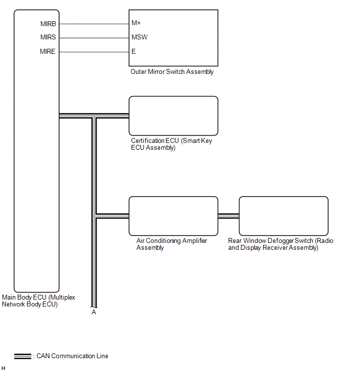
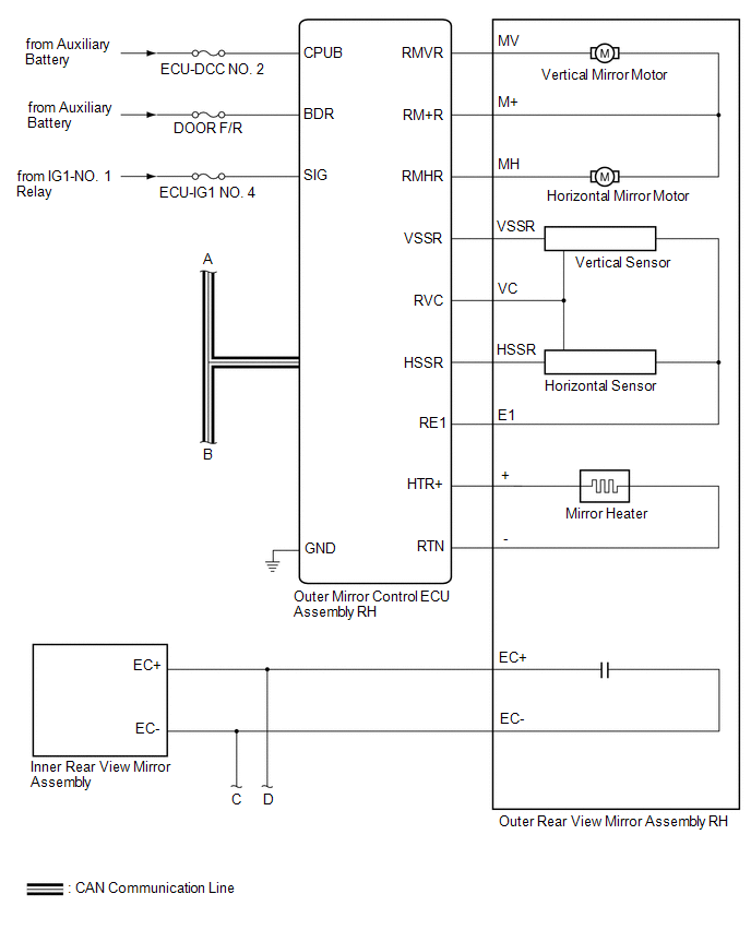
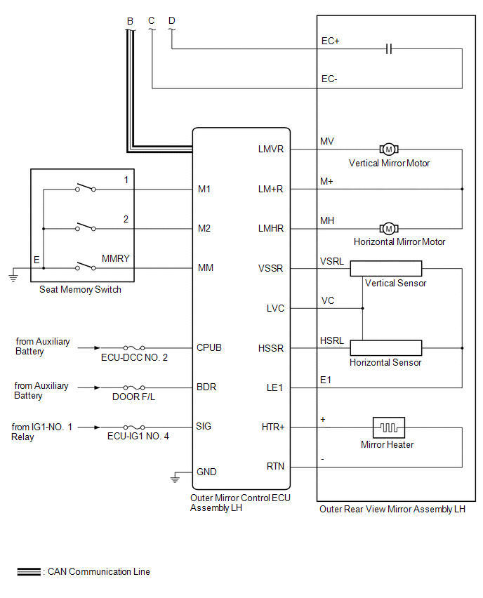 Communication Table
Sender | Receiver | Signal | Line |
|---|---|---|---|
Air Conditioning Amplifier Assembly |
Outer Mirror Control ECU Assembly |
Mirror heater drive request signal |
CAN |
Main Body ECU (Multiplex Network Body ECU) |
Outer Mirror Control ECU Assembly |
|
CAN |
Outer Mirror Control ECU Assembly |
Main Body ECU (Multiplex Network Body ECU) |
|
CAN |
Certification ECU (Smart Key ECU Assembly) |
Main Body ECU (Multiplex Network Body ECU) |
Key ID signal |
CAN |
Radio and Display Receiver Assembly |
Air Conditioning Amplifier Assembly |
Mirror heater switch (rear window defogger switch) operation signal |
CAN |
Terminals Of Ecu
TERMINALS OF ECU
CHECK OUTER MIRROR CONTROL ECU ASSEMBLY LH
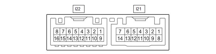
(a) Disconnect the I21 outer mirror control ECU assembly LH connector.
(b) Measure the voltage and resistance according to the value(s) in the table below.
HINT:
Measure the values on the wire harness side with the connector disconnected.
Terminal No. (Symbol) | Wiring Color | Terminal Description | Condition | Specified Condition |
|---|---|---|---|---|
I21-14 (BDR) - Body ground |
GR - Body ground |
+B power supply |
Power switch off |
11 to 14 V |
I21-6 (CPUB) - Body ground |
LA-L - Body ground |
+B power supply |
Power switch off |
11 to 14 V |
I21-5 (SIG) - Body ground |
LA-B - Body ground |
Ignition power supply |
Power switch off → on (IG) |
Below 1 V → 11 to 14 V |
I21-7 (GND) - Body ground |
W-B - Body ground |
Ground |
Always |
Below 1 Ω |
(c) Reconnect the I21 outer mirror control ECU assembly LH connector.
(d) Measure the voltage according to the value(s) in the table below.
Terminal No. (Symbol) | Wiring Color | Terminal Description | Condition | Specified Condition |
|---|---|---|---|---|
I22-1 (LMVR) - I22-10 (LM+R) |
BR - V |
Vertical mirror motor drive voltage |
Driver door mirror surface moving upward → stopped |
11 to 14 V → Below 1 V |
I22-10 (LM+R) - I22-1 (LMVR) |
V - BR |
Vertical mirror motor drive voltage |
Driver door mirror surface moving downward → stopped |
11 to 14 V → Below 1 V |
I22-10 (LM+R) - I22-9 (LMHR) |
V - LG |
Horizontal mirror motor drive voltage |
Driver door mirror surface moving right → stopped |
11 to 14 V → Below 1 V |
I22-9 (LMHR) - I22-10 (LM+R) |
LG - V |
Horizontal mirror motor drive voltage |
Driver door mirror surface moving left → stopped |
11 to 14 V → Below 1 V |
I22-5 (LVC) - I22-14 (LE1) |
G - BR |
Mirror position sensor power supply |
Power switch on (IG) |
4.55 to 5.45 V |
Power switch off |
Below 1 V |
|||
I22-6 (VSSR) - I21-7 (GND) |
V - W-B |
Mirror position sensor signal |
Power switch on (IG) |
0 to 5 V |
I22-13 (HSSR) - I21-7 (GND) |
GR - W-B |
Mirror position sensor signal |
Power switch on (IG) |
0 to 5 V |
I21-3 (M2) - I21-7 (GND) |
R - W-B |
M2 switch signal for seat memory switch |
M2 switch on |
Below 1 V |
M2 switch off |
11 to 14 V |
|||
I21-2 (M1) - I21-7 (GND) |
BR - W-B |
M1 switch signal for seat memory switch |
M1 switch on |
Below 1 V |
M1 switch off |
11 to 14 V |
|||
I21-1 (MM) - I21-7 (GND) |
GR - W-B |
SET switch signal for seat memory switch |
SET switch on |
Below 1 V |
SET switch off |
11 to 14 V |
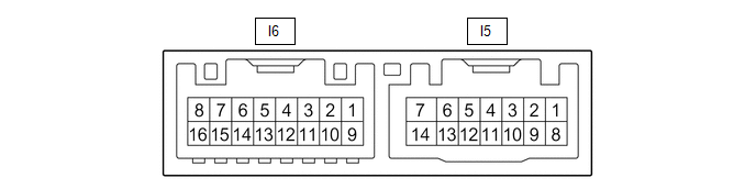
CHECK OUTER MIRROR CONTROL ECU ASSEMBLY RH
(a) Disconnect the I5 outer mirror control ECU assembly RH connector.
(b) Measure the voltage and resistance according to the value(s) in the table below.
HINT:
Measure the values on the wire harness side with the connector disconnected.
Terminal No. (Symbol) | Wiring Color | Terminal Description | Condition | Specified Condition |
|---|---|---|---|---|
I5-14 (BDR) - Body ground |
GR - Body ground |
+B power supply |
Power switch off |
11 to 14 V |
I5-6 (CPUB) - Body ground |
LA-L - Body ground |
+B power supply |
Power switch off |
11 to 14 V |
I5-5 (SIG) - Body ground |
LA-B - Body ground |
Ignition power supply |
Power switch off → on (IG) |
Below 1 V → 11 to 14 V |
I5-7 (GND) - Body ground |
W-B - Body ground |
Ground |
Always |
Below 1 Ω |
(c) Reconnect the I5 outer mirror control ECU assembly RH connector.
(d) Measure the voltage according to the value(s) in the table below.
Terminal No. (Symbol) | Wiring Color | Terminal Description | Condition | Specified Condition |
|---|---|---|---|---|
I6-1 (RMVR) - I6-10 (RM+R) |
BR - V |
Vertical mirror motor drive voltage |
Front passenger door mirror surface moving upward → stopped |
11 to 14 V → Below 1 V |
I6-10 (RM+R) - I6-1 (RMVR) |
V - BR |
Vertical mirror motor drive voltage |
Front passenger door mirror surface moving downward → stopped |
11 to 14 V → Below 1 V |
I6-10 (RM+R) - I6-9 (RMHR) |
V - LG |
Horizontal mirror motor drive voltage |
Front passenger door mirror surface moving right → stopped |
11 to 14 V → Below 1 V |
I6-9 (RMHR) - I6-10 (RM+R) |
LG - V |
Horizontal mirror motor drive voltage |
Front passenger door mirror surface moving left → stopped |
11 to 14 V → Below 1 V |
I6-5 (RVC) - I6-14 (RE1) |
G - BR |
Mirror position sensor power supply |
Power switch on (IG) |
4.55 to 5.45 V |
Power switch off |
Below 1 V |
|||
I6-6 (VSSR) - I5-7 (GND) |
V - W-B |
Mirror position sensor signal |
Power switch on (IG) |
0 to 5 V |
I6-13 (HSSR) - I5-7 (GND) |
GR - W-B |
Mirror position sensor signal |
Power switch on (IG) |
0 to 5 V |
CHECK MAIN BODY ECU (MULTIPLEX NETWORK BODY ECU) AND INSTRUMENT PANEL JUNCTION BLOCK ASSEMBLY
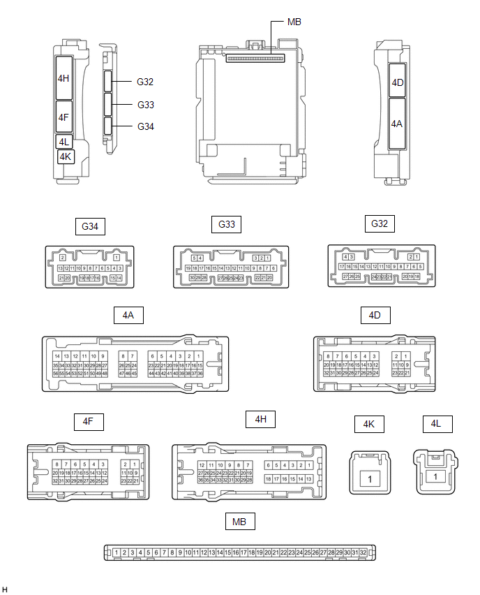
(a) Disconnect the instrument panel junction block assembly and main body ECU (multiplex network body ECU) connectors.
Click here 
(b) Reconnect the instrument panel junction block assembly connectors.
(c) Measure the resistance and voltage according to the value(s) in the table below.
HINT:
Measure the values on the wire harness side with the connector disconnected.
Terminal No. (Symbol) | Wiring Color | Terminal Description | Condition | Specified Condition |
|---|---|---|---|---|
MB-31 (BECU) - Body ground |
- |
Auxiliary battery power supply |
Power switch off |
11 to 14 V |
MB-32 (IG) - Body ground |
- |
Ignition power supply (IG signal) |
Power switch on (IG) |
11 to 14 V |
Power switch off |
Below 1 V |
|||
MB-30 (ACC) - Body ground |
- |
Ignition power supply (ACC signal) |
Power switch on (ACC) |
11 to 14 V |
Power switch off |
Below 1 V |
|||
MB-11 (GND1) - Body ground |
- |
Ground |
Always |
Below 1 Ω |
G32-19 (GND2) - Body ground |
W-B - Body ground |
Ground |
Always |
Below 1 Ω |
(d) Connect the main body ECU (multiplex network body ECU) connectors.
(e) Measure the voltage according to the value(s) in the table below.
Tester Connection | Wiring Color | Terminal Description | Condition | Specified Condition |
|---|---|---|---|---|
G34-7 (MIRB) - G34-9 (MIRE) |
L - W |
Mirror surface adjust switch signal |
|
Below 1.7 V |
|
Below 2.7 V |
|||
|
Below 3.5 V |
|||
|
Below 4 V |
|||
|
3.8 to 5 V |
|||
G34-8 (MIRS) - G34-9 (MIRE) |
GR - W |
Mirror select switch signal |
|
Below 2 V |
|
Below 1 V |
|||
|
3.8 to 5.0 V |
Lost Communication With Body Control Module "B" (U0142)
DESCRIPTION
DTC No. | Detection Item | DTC Detection Condition | Trouble Area |
|---|---|---|---|
U0142 |
Lost Communication with Main Body ECU |
No communication with main body ECU (multiplex network body ECU) |
|
PROCEDURE
GO TO CAN COMMUNICATION SYSTEM
HINT:
Refer to CAN Communication System.
Click here 
| NEXT |  |
END |