Side Turn Signal Light Assembly
Components
COMPONENTS
ILLUSTRATION
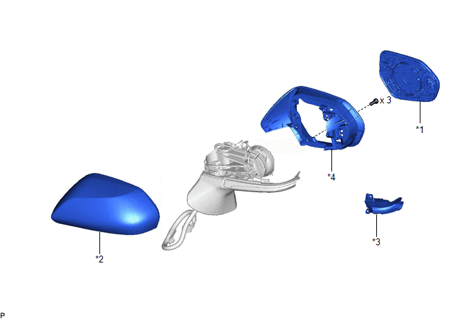
*1 |
OUTER MIRROR |
*2 |
OUTER MIRROR COVER |
*3 |
SIDE TURN SIGNAL LIGHT ASSEMBLY |
*4 |
VISOR HOUSING |
Inspection
INSPECTION
PROCEDURE
1. INSPECT SIDE TURN SIGNAL LIGHT ASSEMBLY LH
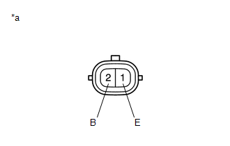
*a |
Component without harness connected (Side Turn Signal Light Assembly LH) |
(a) Apply auxiliary battery voltage to the side turn signal light assembly LH and check that the light illuminates.
OK:
Measurement Condition | Specified Condition |
|---|---|
Auxiliary battery positive (+) → Terminal 2 (B) Auxiliary battery negative (-) → Terminal 1 (E) |
Side turn signal light illuminates |
If the result is not as specified, replace the side turn signal light assembly LH.
2. INSPECT SIDE TURN SIGNAL LIGHT ASSEMBLY RH
*a |
Component without harness connected (Side Turn Signal Light Assembly RH) |
(a) Apply auxiliary battery voltage to the side turn signal light assembly RH and check that the light illuminates.
OK:
Measurement Condition | Specified Condition |
|---|---|
Auxiliary battery positive (+) → Terminal 2 (B) Auxiliary battery negative (-) → Terminal 1 (E) |
Side turn signal light illuminates |
If the result is not as specified, replace the side turn signal light assembly RH.
Installation
INSTALLATION
HINT:
- Use the same procedure for the RH side and LH side.
- The following procedure is for the LH side.
PROCEDURE
1. INSTALL SIDE TURN SIGNAL LIGHT ASSEMBLY
(a) Engage the 2 guides.
(b) Engage the 2 claws to install the side turn signal light assembly.
2. INSTALL VISOR HOUSING
Click here 
3. INSTALL OUTER MIRROR COVER
Click here
4. INSTALL OUTER MIRROR
Click here
5. INSTALL OUTER REAR VIEW MIRROR ASSEMBLY WITH COVER
Click here
6. PERFORM CALIBRATION (w/ Panoramic View Monitor System)
for Gasoline Model:
Click here
for HV Model:
Click here
Removal
REMOVAL
The necessary procedures (adjustment, calibration, initialization, or registration) that must be performed after parts are removed and installed, or replaced during side turn signal light assembly removal/installation are shown below.
Necessary Procedure After Parts Removed/Installed/Replaced (for Gasoline Model)Replaced Part or Performed Procedure | Necessary Procedure | Effect/Inoperative Function when Necessary Procedure not Performed | Link |
|---|---|---|---|
|
Side television camera view adjustment |
Panoramic view monitor system |
 |
Replaced Part or Performed Procedure | Necessary Procedure | Effect/Inoperative Function when Necessary Procedure not Performed | Link |
|---|---|---|---|
|
Side television camera view adjustment |
Panoramic view monitor system |
|
HINT:
- Use the same procedure for the RH side and LH side.
- The following procedure is for the LH side.
PROCEDURE
1. REMOVE OUTER REAR VIEW MIRROR ASSEMBLY WITH COVER
Click here
2. REMOVE OUTER MIRROR
Click here
3. REMOVE OUTER MIRROR COVER
Click here
4. REMOVE VISOR HOUSING
Click here
5. REMOVE SIDE TURN SIGNAL LIGHT ASSEMBLY
(a) Disengage the 2 claws. |
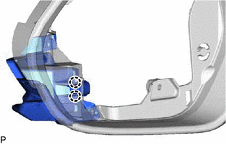 |
(b) Disengage the 2 guides to remove the side turn signal light assembly. |
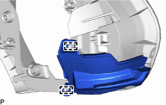 |