Vehicle Approaching Speaker
Components
COMPONENTS
ILLUSTRATION
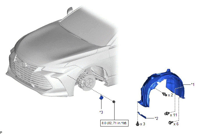
*1 |
FRONT FENDER SPLASH SHIELD SUB-ASSEMBLY LH |
*2 |
FRONT WHEEL OPENING EXTENSION PAD LH |
*3 |
VEHICLE APPROACHING SPEAKER ASSEMBLY |
- |
- |
 |
N*m (kgf*cm, ft.*lbf): Specified torque |
- |
- |
Inspection
INSPECTION
PROCEDURE
1. INSPECT VEHICLE APPROACHING SPEAKER ASSEMBLY
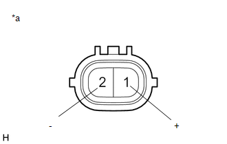
(a) Measure the resistance according to the value(s) in the table below. Standard Resistance:
HINT: Make sure that the vehicle approaching speaker assembly is securely installed and not loose. If the result is not as specified, replace the vehicle approaching speaker assembly. |
|
Installation
INSTALLATION
PROCEDURE
1. INSTALL VEHICLE APPROACHING SPEAKER ASSEMBLY
(a) Connect the connector. |
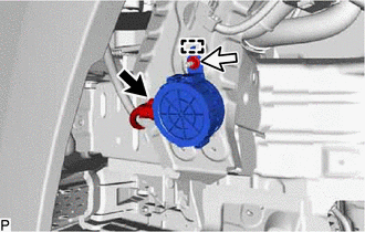 |
(b) Engage the guide.
(c) Install the vehicle approaching speaker assembly with the nut.
Torque:
8 N·m {82 kgf·cm, 71 in·lbf}
2. INSTALL FRONT FENDER SPLASH SHIELD SUB-ASSEMBLY LH
HINT:
Use the same procedure as for the RH side.
Click here 
3. INSTALL FRONT WHEEL OPENING EXTENSION PAD LH
HINT:
Use the same procedure as for the RH side.
Click here
4. INSTALL FRONT WHEEL LH
Click here
Removal
REMOVAL
PROCEDURE
1. REMOVE FRONT WHEEL LH
Click here 
2. REMOVE FRONT WHEEL OPENING EXTENSION PAD LH
HINT:
Use the same procedure as for the RH side.
Click here
3. REMOVE FRONT FENDER SPLASH SHIELD SUB-ASSEMBLY LH
HINT:
Use the same procedure as for the RH side.
Click here
4. REMOVE VEHICLE APPROACHING SPEAKER ASSEMBLY
(a) Remove the nut. |
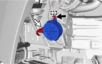 |
(b) Disengage the guide.
(c) Disconnect the connector to remove the vehicle approaching speaker assembly.