Installation
Check the engine mounts and the coolant, oil and fuel hoses for porosity or cracks. Replace if necessary.
If the engine/transmission was separated, check the clutch driven plate for sufficient lining thickness and lining condition. If wear is advanced or mileage is high, replace the clutch completely. If the clutch release bearing made noise when the clutch pedal was pressed, replace the bearing.
Clean the clutch release bearing and the drive shaft splines, and apply a thin coat of MoS2 grease.
Check that both locating dowels for centering the engine and transmission are present in the engine block. Fit locating sleeves if necessary, see page 131.
Insert the engine/transmission connecting bolts and tighten them alternately to the correct tightening torque.
Caution: the tightening torque of the bolts depends on the outer thread diameter.
Torque for M12 bolts (Ø 12 mm): 80 N·m; for M10 bolts: 35 N·m; for M8 bolts: 25 N·m.
Install the starter motor, see page 261.
Carefully guide the engine and transmission into the engine compartment from below using a workshop crane. When lifting, guide the engine carefully to avoid damage to the body.
Screw on the two side engine mounts and the center engine mount hand-tight. Do not tighten them yet.
Remove the crane.
Align the engine so that it is free of stress by rocking it.
Then tighten the mounting bolts of all 3 engine mounts in the following order: first the right engine mount (engine side), then the left mount (transmission side), then the center mount. The bolt torque depends on the respective thread diameter: M8 thread: 35 N·m, M10 thread: 50 N·m, M12 thread: 90 N·m.
Insert the driveshafts into the wheel hubs. Tighten the new hub nut only when the vehicle is standing on the ground.
Bolt the strut to the steering knuckle using new self-locking nuts. Tighten the nuts to 70 N·m.
Route the brake hose and the ABS wheel speed sensor cable through the brackets on the strut.
Bolt the tie rods to the steering knuckle, see page 162.
Connect the power steering pump and fill with power steering fluid, see page 164.
Where fitted, insert the speedometer cable and tighten the union nut to the transmission.
Bolt the shift linkage to the transmission using new nuts and 15 N·m.
Install the front exhaust pipe, see page 121.
Fit the trim in the left wheel housing and insert the clips or screws.
Position the front wheels so that the marks made during removal align. Before fitting, lightly grease the wheel centering seat and the conical surface of the wheel bolts with roller bearing grease. Do not grease or oil the wheel bolt threads. Fit the wheels. Lower the vehicle and tighten the wheel bolts crosswise to 90 N·m.
Engage a gear, apply the parking brake, and depress the foot brake.
Then tighten the new hub nuts for the driveshafts as specified and stake the collar onto the driveshaft, see page 146.
Install the radiator, see page 78.
Connect the vacuum hoses for the brake booster, fuel vapor and pressure sensor to the intake manifold according to the marks made.
Fit the battery bracket and bolt it in place.
Bolt the relay box to the battery bracket with 2 nuts.
Place the cover on the relay box and secure it with 1 screw.
Install the engine control unit, see page 89.
Connect all electrical wiring, coolant hoses and fuel hoses according to the marks made. Secure the hoses with new hose clamps. Secure the electrical wiring with cable ties.
Bolt the fuel line retaining bracket to the engine intake manifold, see illustration T-10188 under "Removal".
Fit the cover for the pressure sensor to the engine bulkhead and secure it with the screw.
Hook in the throttle cable, see page 98.
Check the oil level in the engine and transmission and top up if necessary, see chapter "Maintenance".
Fill the coolant and check the antifreeze protection, see page 71.
Hook in and adjust the clutch cable, see page 128.
Install the air filter and intake hoses.
Install the battery. Connect the positive cable (+) first, then the negative cable (-) to the battery. Set the clock if fitted and enter the radio anti-theft code.
Vehicles with air conditioning: bolt on the refrigerant lines and have the air conditioning system refilled by a specialist workshop.
Bring the engine to operating temperature, check the coolant level and check all hose connections for leaks.
Have the wheel alignment checked and adjusted as soon as possible, see page 167.
Remove both driveshafts, see page 146.

Use a screwdriver to lift the gear selector cable off the ball joint of the transmission lever, arrow. Pull the retaining fork off the counter bearing upwards.
Remove both driveshafts, see page 146.
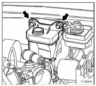
Unscrew the power steering fluid reservoir and hang it on the engine with wire.
Remove the right trim panel below the windshield, see page 283.
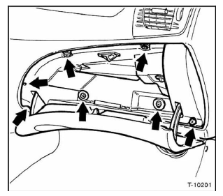
Remove the glove box. To do so, remove the screws (arrows), disconnect the cable from the relay holder behind the glove box and route it through to the engine compartment.
Remove the front right inner fender liner, see page 204.
Disconnect the connector from the activated charcoal filter valve in the right front fender.
Caution: on the 2.0 L petrol engine, the front axle subframe must be removed before the transmission is removed.
The power steering housing, the anti-roll bar and the front suspension wishbones must first be removed from the subframe. A suitable support tool is required to remove the subframe so that it does not drop down after the fastening bolts are loosened. We therefore recommend having this work carried out at a specialist workshop.Observe the notes for the 1.8 L engine. In addition:

Remove the clutch slave cylinder of the hydraulic clutch actuation, bolts (2 upper arrows). Remove the transmission earth cable, bolt (lower arrow).
Test yourself
A quick Fiat Bravo quiz: every answer comes with an explanation and a link to the manual page.