Central locking
The electric central locking system consists of four actuator motors integrated into the locks of the four doors.
The system is controlled by a control unit installed behind the glove box. When the front doors are locked or unlocked, or when the remote control is operated, the control unit causes the locks of all doors to be locked or unlocked simultaneously.
The electronic control unit has a safety circuit that interrupts the power supply to the actuator motors 15 to 35 seconds after a lock or unlock command.
This prevents the actuator motors from burning out if they are energised continuously, for example if a switch sticks.
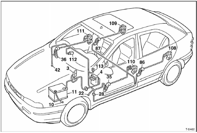
The illustration shows the version without the theft warning system for models S - SX - GT.
3 - Fuse box, power circuits:
30 A fuse for ignition and fuel injection (petrol engine) or 60 A fuse for glow plugs (diesel)
40 A fuse for ignition switch
60 A fuse for optional equipment
80 A fuse, fuse and relay panel (central electrical system)
Fuse and relay panel
10 - Battery earth on body
11 - Battery
22 - Earth on instrument panel, left
28 - Cable connection, instrument panel / rear door locking
35 - Cable connection, instrument panel / front door, left
36 - Cable connection, instrument panel / front door, right
42 - Earth on instrument panel, right
86 - Cable connection, longitudinal / rear door, left
87 - Cable connection, longitudinal / rear door, right
108 - Locking actuator, rear left / "theft warning system on" switch
109 - Locking actuator, rear right / "theft warning system on" switch
110 - Locking actuator, front left / "theft warning system on" switch
111 - Locking actuator, front right / "theft warning system on" switch
112 - Door locking control unit
113 - 20 A fuse for central locking
Test yourself
A quick Fiat Bravo quiz: every answer comes with an explanation and a link to the manual page.