Brake Booster
GENERAL INFORMATION
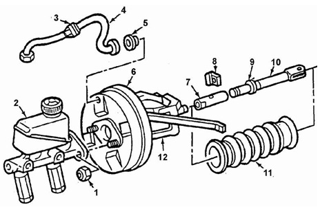
Brake Booster
1. MASTER CYLINDER MOUNTING NUT.
2. MASTER CYLINDER ASSEMBLY.
3. CHECK VALVE.
4. VACUUM HOSE.
5. HOSE RUBBER BUSHING.
6. BRAKE BOOSTER HOUSING.
7. Adjusting sleeve of brake pedal pushrod.
8. Adjusting sleeve lock.
9. NUT.
10. Brake pedal pushrod.
11. Protective boot.
12. Bracket
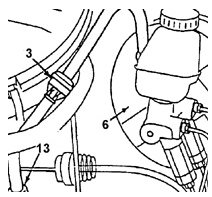
Location of vacuum hose.
3. CHECK VALVE.
6. Vacuum booster housing.
13. Nut securing vacuum hose to engine intake manifold
The vehicle is equipped with a vacuum brake booster with one diaphragm.
In the released brake state, vacuum is maintained in both chambers of the booster, separated by the diaphragm. When braking, atmospheric air is admitted into the rear chamber of the booster, which applies additional force to the diaphragm and the master cylinder piston. After the brake pedal is released,
the rear chamber of the booster is disconnected from the atmosphere and connected
through a check valve to the engine intake manifold, which is the vacuum source.
With the engine off, depress the brake pedal several times to reduce the vacuum in the booster. Then press and hold the brake pedal down. Start the engine.
Inspection
PROCEDURE.
If the booster is serviceable, the brake pedal moves further down when the engine starts.
If the pedal remains in place, the possible cause is a fault in the vacuum system: check valve, hose, etc. Check the vacuum system.
Removal of adjusting sleeve lock A. SCREWDRIVER.
Removal of adjusting sleeve.
8. Adjusting sleeve lock
9. Nut
Remove or disconnect
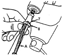 1. Remove the master cylinder from the booster housing. Unscrew the nuts and move the master cylinder slightly forward. Do not disconnect the brake lines from the master cylinder.
7. Adjusting sleeve of brake pedal pushrod.
2. Remove nut 13 securing the vacuum hose to the intake manifold.
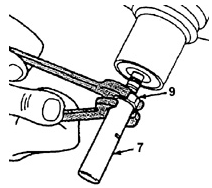 3. Disconnect the vacuum hose from the booster housing.
7. Adjusting sleeve of brake pedal pushrod.
4. Disconnect the stop lamp switch.
PROCEDURE.
5. Remove the brake pedal spring.
6. Remove the retaining clip and pull out the brake pedal pushrod pin.
7. On a vehicle without power steering, unscrew the nuts securing the pedal bracket to the dash panel.
On a vehicle with power steering, unscrew the lower mounting bolt located behind the hydraulic lines.
8. Tilt the booster housing and bracket slightly and remove them upward from the dash panel.
9. Remove the bracket from the booster housing.
10. Remove protective boot 11 from the booster.
11. Remove lock 8 from sleeve 7.
12. Pushrod.
13. Unscrew and remove sleeve 7 from the piston pushrod.
On vehicles with power steering, remove the lower mounting bolt located behind the hydraulic lines.
14. Unscrew nut 9.
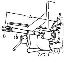
Measurement of pushrod length A. DISTANCE 278.5 mm.
B. CLEVIS PIN HOLE.
10. Brake pedal pushrod
1. Install the new booster in a vise. Use protective pads.
7..
2. Screw on nut 9, install sleeve 7 onto the piston pushrod.
10..
3. Insert pushrod 10 into sleeve 7 and install lock 8.
4. Adjust the position of the adjusting sleeve. The distance from the booster housing to the axis of the pushrod clevis hole must be 278.5 mm (see figure Measurement of pushrod length).
9..
Install or connect
 5. Install protective boot 11.
B. CLEVIS PIN HOLE.
6. Vacuum booster housing.
10. BRAKE PEDAL PUSH ROD
PROCEDURE.
1. Install the new booster in a vise. Use protective pads.
10. Insert the pin into the pushrod clevis hole and the brake pedal.
11. Install the pedal pin retaining clip and the brake pedal spring.
8..
12. Stop lamp switch.
516. MODULATOR HOUSING WITH ELECTROMECHANICAL DRIVE.
Spring brake.
11..
6. Bracket to booster housing. Tighten the nuts to 22 N·m.
7. Booster with bracket to dash panel. Tighten the nuts to 22 N·m.
8. Master cylinder to booster. Tighten the nuts to 18 N·m.
9. Connect the vacuum hose to the booster and intake manifold. Tighten the hose retaining nut at the intake manifold to 15 N·m.
506. DRIVE GEAR.
505. SPRING RETAINING RING.
502. CHECK BALL VALVE (IN OPEN POSITION).
Test yourself
A quick Daewoo Nexia quiz: every answer comes with an explanation and a link to the manual page.