Drum brake
GENERAL INFORMATION
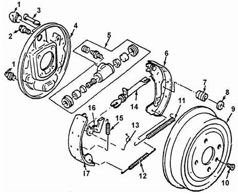
Drum Brake
1. BACKING PLATE HOLE PLUG.
2. WHEEL CYLINDER MOUNTING BOLT.
3. HOLD-DOWN PIN.
4. BACKING PLATE.
5. WHEEL CYLINDER ASSEMBLY.
6. REAR BRAKE SHOE.
7. HOLD-DOWN SPRING.
8. HOLD-DOWN WASHER.
9. BRAKE DRUM.
10. STOP SCREW.
11. UPPER RETURN SPRING.
12. LOWER RETURN SPRING.
13. LINK.
14. ADJUSTER ASSEMBLY.
15. ADJUSTER SPRING.
16. ADJUSTER LEVER.
17. FRONT BRAKE SHOE.
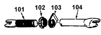
Adjuster
101. THREADED ROD.
102. NUT.
103. CLAMP.
104. HOLLOW ROD
The vehicle is equipped with rear drum brake assemblies with a leading shoe and a trailing shoe.
In the released position, the upper ends of the shoes are pressed against the pistons by springs, and the lower ends against the stop located on the backing plate.
certain value. This limits the brake torque of the rear wheels and the risk of their locking during intensive braking. Such brake force regulators are usually used on vehicles equipped with
front disc and rear drum brake assemblies.
The self-energizing action of the shoe. When braking a vehicle moving in reverse,
the rear shoe becomes the leading shoe and the front shoe becomes the trailing shoe. The forces acting on the shoes from the pistons and the brake drum are absorbed by the stop on the
non-rotating backing plate. The backing plate is attached to the corresponding rear suspension arm.
Brake clearance adjustment in the brake
assembly is performed automatically at each service brake application. For
drum brake assemblies with leading and trailing shoes, more
intensive wear of the front leading shoe compared to the rear trailing shoe is typical. It is not recommended to reuse used brake shoes, as this may disrupt the automatic brake adjustment and increase
brake pedal free travel..
When servicing drum brake assemblies, all
parts included in the repair kit must be replaced..
Lubricate parts according to the supplied instructions..
It is prohibited to use compressed air from the plant line to blow off and dry parts, as oil droplets contained in it may damage the rubber seals..
After any work involving removal or disconnection of any
brake hydraulic lines or hoses, bleed air from the corresponding circuit or from the entire brake system..
Brake shoes must be replaced only as a complete set on both brake assemblies..
Torque values for threaded connections are given for dry, unlubricated fasteners.
parts..
All repair work must be carried out on a clean workbench to prevent
contamination of brake system parts with mineral oils, greases and
fluids..
Warning.
Brake lining material contains asbestos fibers, which get into the
human respiratory system and are hazardous to health. Therefore, when
performing brake maintenance and repair, avoid operations such as cleaning lining wear residue from parts with a dry brush or a jet of
compressed air, sanding of shoes, etc., which generate dust. To
remove fine dust particles from brake assemblies, use a
cloth dampened with water..
Remove or disconnect:
PROCEDURE.
1. Raise the vehicle.
2. Rear wheels. Mark the position of the rear wheels relative to the hubs..
3. Nuts of the heat shield. Place the shield on the muffler..
4. Release the parking brake cable attachment..
5. Unscrew the brake drum stop screw..
6. Brake drum.
If drum removal is difficult:
– make sure the parking brake is released.
– release the parking brake cable attachment.
– remove plug 1 from the hole in backing plate 4 and move with a screwdriver
the parking brake expander lever until it stops against the rear brake shoe
6..
7. Upper and lower return springs 11,
12..
8. Regulator return spring 15 and regulator actuating lever
16..
9. Regulator assembly
14..
10. Pin 3, spring 7 and retainer washer 8..
11. Rear brake shoe
6..
Clean.
PROCEDURE.
1. Adjuster components..
2. Apply brake component grease to the threads. Check.
PROCEDURE.
1. Smooth rotation of the threaded rod in the nut.
2. If there are signs of overheating, wear or other defects, replace the defective parts..
Warning.
Before installing the brake drum, make sure that nut 102
is screwed fully onto rod 101. The nut must not be seized on the rod thread..
Install or connect

Lubrication points on the brake backing plate
PROCEDURE.
1. Apply grease to the projections of brake backing plate 4 at the points of contact with the
shoes (see figure Lubrication points on the brake backing plate)..
2. Parking brake actuating lever 18 to the parking brake cable end fitting..
3. Rear brake shoe 6 onto backing plate 4, pin, spring and retainer washer..
Check the correct position of the parking brake cable..
4. Adjuster 14, front shoe 17 and lower return spring
12. Tighten the heat shield mounting nuts..
Warning.
Do not overstretch the lower return spring
12. Spring 12 must
be located under the stop of the brake disc..
5. Pin, spring and retainer washer..
6. Adjuster
14..
6a. Fully screw the adjuster rod into the nut..
6b. Install the adjuster..
6c. Turn clamp 103 toward the brake backing plate
4..
7. Install adjuster actuating lever 16 on the pivot and fit the spring
15..
Warning.
Do not overstretch adjuster spring 15..
8. Insert one end of link 13 into the hole in the lever 16 pivot, and the other end into the hole
of the front brake shoe..
9. Install the upper return spring, securing its ends to link 13 and rear shoe 6. Warning.
Do not overstretch the upper return spring
12..
10. Brake drum 9 and set screw
10..
11. Rear wheels..
12. Adjust the parking brake.
Test yourself
A quick Daewoo Nexia quiz: every answer comes with an explanation and a link to the manual page.