Anti-lock brake system
GENERAL INFORMATION
 508. BRAKE SPRING.
509. DRIVE CAM CLUTCH.
510. ELECTRIC MOTOR SHAFT.
511. ELECTRIC MOTOR HOUSING.
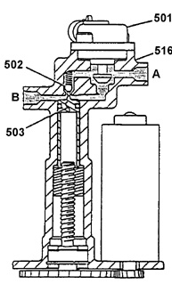
Front wheel modulator – ABS braking operation A. MODULATOR INLET (FROM MASTER CYLINDER).
501. NORMALLY OPEN SOLENOID VALVE (IN CLOSED POSITION).
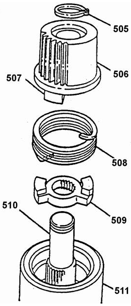
Spring brake
502. CHECK BALL VALVE (IN CLOSED POSITION).
Rear wheel modulator – ABS braking operation A. MODULATOR INLET (FROM MASTER CYLINDER).
List of abbreviations.
ABS Anti-lock Brake System.
509. DRIVING DOG CLUTCH.
B+ Battery voltage.
507. GEAR CAM.

Front wheel modulator – braking during ABS operation A. MODULATOR INLET (FROM MASTER CYLINDER).
509. DRIVE CAM CLUTCH.
501. NORMALLY OPEN SOLENOID VALVE (SHOWN IN CLOSED POSITION).
502. CHECK BALL VALVE (SHOWN IN CLOSED POSITION).
Front wheel modulator – ABS braking operation A. MODULATOR INLET (FROM MASTER CYLINDER).
501. NORMALLY OPEN SOLENOID VALVE (IN CLOSED POSITION).
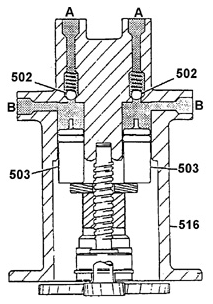
Rear wheel modulator – braking during ABS operation A. MODULATOR INLET (FROM MASTER CYLINDER).
509. DRIVE CAM CLUTCH.
502. CHECK BALL VALVE (SHOWN IN CLOSED POSITION).
Front wheel modulator – ABS braking operation A. MODULATOR INLET (FROM MASTER CYLINDER).
501. NORMALLY OPEN SOLENOID VALVE (IN CLOSED POSITION).
List of abbreviations.
ABS Anti-lock Brake System.
B+ Battery voltage.
DTC: Diagnostic Trouble Code.
ABS ECU: Electronic Control Unit for Braking.
SV: Solenoid Valve.
During emergency braking, when wheel lock-up is most likely, the electronic
brake control unit (ABS ECU) automatically regulates
brake fluid pressure in the hydraulic circuit of each front wheel (individually) and in the
rear wheel circuit (synchronously). The ABS ECU ensures braking of the wheels without lock-up
and thereby reduces the risk of vehicle skidding and improves stability and handling
of the vehicle during emergency braking. It should be noted that the ABS VI system cannot increase brake fluid pressure in the wheel cylinders compared with
the pressure in the master cylinder, which depends entirely on brake pedal force. ABS operates in the speed range from 5 km/h to maximum
vehicle speed.
During normal service braking under ordinary road conditions, the brake system
operates in the basic mode: when the brake pedal is pressed, the vacuum booster is activated and the master cylinder pistons force brake fluid into the wheel cylinders. Each of the two ABS channels serving the front wheels includes a separate modulator with electromechanical drive. The modulator consists of a housing with hydraulic passages, a solenoid valve (SV), a ball check valve, a piston with ball nut, and a lead screw.
The electromechanical drive consists of an electric motor, a spring brake,
and a gear train. In the basic braking mode, the piston is in its uppermost position. Moving the piston to this position is provided by
the electromechanical drive via a ball screw. The spring brake is used to lock
the piston in the upper position. The brake consists of a coil spring with two inward-bent tangs, inserted with a small clearance
into the cylindrical bore of the motor housing. The spring is fitted on the shaft
of the motor and is located between the drive dog clutch and the gear with an end
dog clutch. The dogs of the drive clutch and gear engage with the corresponding tangs of the spring (see Figure Spring Brake).
In basic braking mode, a force directed downward acts on the piston from the brake fluid side. This force is converted by the ball screw mechanism into torque,
which is transmitted to the motor gear and the brake spring and acts counterclockwise. The torque causes the spring to wind and expand radially,
its coils pressing against the bore wall and braking the gear. With the piston in the upper position, the ball check valve is open. When
braking in the basic mode, brake fluid flows to the wheel cylinder through two paths: through the check valve opened by the piston and through the normally open SV. This allows the vehicle to be braked if the ABS fails (piston does not return to the upper position) or when the system is de-energized (see Figure
Front Wheel Modulator – Basic Braking Mode).
The rear wheel modulator operates similarly, with the following exceptions.
Both rear wheels are controlled synchronously and, in addition, the rear modulator design has no SV. Synchronous rear wheel brake control made it possible
to use one electromechanical drive instead of two and simplify the ABS design. For rear wheel brake control, the "Select Low" principle is used,
which provides simultaneous release of both rear wheels when
lock-up of either one begins. This principle provides good lateral stability of the vehicle during braking. The absence of an SV in the rear wheel modulator is because the rear wheels contribute relatively little to braking effectiveness, and if the ABS fails, the vehicle can be braked with the specified deceleration by the front wheels alone. If the ABS fails in a way that disables the rear wheel brake circuits, the ABS ECU sets the corresponding DTC and
illuminates both warning lamps: the yellow "ABS" lamp and the red "BRAKE" lamp.
ABS begins operating only with the stop lamp switched on, after
the ABS ECU microprocessor detects the onset of lock-up of at least one of the wheels
of the vehicle. In this case, the ABS ECU uses the modulator to regulate brake fluid pressure in the brake circuit of the corresponding wheel (or wheels) to prevent its lock-up and maintain vehicle stability and
controllability. Pressure regulation cycles repeat several times per second. It should be noted that the ABS VI system cannot increase brake fluid pressure
in the wheel cylinders compared with the pressure in the master
cylinder, which depends entirely on brake pedal force. As a result of ABS operation, braking efficiency, directional stability and controllability during braking are improved under various road conditions. When wheel lock-up begins, the ABS ECU controls the motors and SVs of the three modulators. When the front wheel modulator is activated, on command from the ABS ECU, the SV
closes the flow passage of one of the channels connecting the wheel brake cylinder with the master cylinder (see Figure Front Wheel Modulator – Braking During
ABS Operation). Then the ABS ECU regulates pressure in the isolated wheel circuit by
controlling the modulator piston drive motor. When the
motor is energized, the brake spring winds with simultaneous radial
compression of the coils and releases the drive gear (see Figure Spring Brake). When the piston is lowered, the check valve closes, fully isolating the wheel
brake cylinder from the master cylinder. Pressure in the wheel cylinder depends on the volume of the modulator piston chamber above the piston. Reducing brake pressure in the wheel circuit is achieved by lowering the modulator piston. To increase pressure
of the brake fluid, the piston rises. The piston movement is performed by
ball-screw drive and electromechanical modulator actuator. If a wheel has started to lock on a slippery surface (for example, on ice) at low brake line pressure, and then during the ABS apply phase this wheel moves onto
a road surface section with a high coefficient of friction, the piston.
of the modulator moves to the extreme upper position and opens the check valve. In this case
the pressure in the wheel cylinder is determined by the pressure in the master
cylinder and the force on the brake pedal. The piston remains in the
upper position until the brake fluid pressure becomes sufficient to lock the wheel, and the ABS does not start a new control cycle.
The maximum pressure level in the wheel cylinder during ABS operation
is limited by the pressure in the master brake cylinder. If during braking with the ABS operating the driver reduces the force on the brake pedal, the check valve opens and part of the fluid flows from the wheel cylinder back into the master brake cylinder. When the ABS is switched off, the modulator piston returns to the upper position and the EMV (on the front wheel modulators) opens. After this, the brake system continues to operate in normal mode. When the ABS is switched on, the rear wheel modulator operates in the same way, except for the absence of EMVs.
The synchronous movement of the pistons during brake fluid pressure control is performed by a single electromechanical drive and ball-screw transmission. Approximately equal brake fluid pressure is maintained in the rear wheel cylinders.
During vehicle braking with ABS operating, if the driver reduces pedal force, the check valve opens and part of the fluid from the wheel cylinder flows back into the
The standard brake system is equipped with one red "BRAKE" warning lamp. The ABS uses two warning lamps: the red "BRAKE" and the yellow "ABS".
Warning Lamp Operation
Daewoo Nexia: Warning Lamp Operation
1. When the ignition is switched on (before starting the engine), the "ABS" warning lamp lights up and goes out after 3 seconds. The "BRAKE" warning lamp also lights up and goes out quickly.
2. When the starter is engaged, both the red "BRAKE" and yellow "ABS" warning lamps must remain on continuously.
vehicle speed 8 km/h. At this time the pistons move to the uppermost position.
The tire size fitted to the vehicle is very important for ABS performance. When replacing tires, use only tires that are identical in size, load rating, construction, and other performance characteristics to the original tires the vehicle was equipped with. Pay attention to the standard tire markings. Replace tires only in complete sets per axle. Fitting other tires to the vehicle may seriously affect ABS performance. The ABS consists of the standard brake system and additional components. The brake system includes the vacuum booster, master brake cylinder, front disc brake assemblies, rear drum brakes with leading and trailing shoes, brake lines and hoses, brake fluid level drop sensor, and the "BRAKE" warning lamp.
The additional ABS components include: hydraulic modulators with electromechanical drives, ECU, power relay, two actuator fuses, four wheel speed sensors (one on each wheel), electrical wiring, control unit, and the "ABS" warning lamp.
The modulator and electromechanical drive consist of a housing, piston, ball-screw transmission, check valve, EMV (front wheels only), electric motor, brake spring, and gear train. The modulator regulates the brake fluid pressure in the wheel cylinder. The microprocessor-based ECU controls the braking of individual wheels. Signals from the wheel speed sensors, brake light switch, and ignition lock are input to the ECU. The actuators of the ABS are powered by the ECU and the battery through a relay, which is switched on by the ECU. Three modulator electric motors, two EMVs, the ABS actuator power relay, and a diagnostic connector are connected to the ECU outputs. The ECU serial data line is connected to terminal M of the diagnostic connector and transmits diagnostic information during system checks. The ECU monitors the wheel speeds of all four wheels. If a wheel begins to lock while the brake pedal is pressed (brake light switch on), the ECU commands the corresponding modulator to reduce brake fluid pressure in that wheel cylinder. The EMV and modulator electric motor are then energized. After the wheel slip is reduced, the ECU commands an increase in wheel cylinder pressure and monitors the change in wheel angular speed. If wheel slip increases again, the ECU commands the wheel to be released once more. These pressure control cycles repeat until the vehicle stops, the brake pedal is released, or there is no longer a risk of the braked wheels locking. In addition to its direct control functions, the ECU performs self-diagnosis and diagnosis of all sensors and actuators connected to its inputs and outputs. If any ABS fault is detected, the ECU sets the corresponding fault code and stores it in non-volatile memory (ROM), where the information is retained even when power is disconnected.
The standard brake system is equipped with one red "BRAKE" warning light. The ABS uses two warning lights: red "BRAKE" and yellow "ABS".
Test yourself
A quick Daewoo Nexia quiz: every answer comes with an explanation and a link to the manual page.