1.6 L engine
Remove air filter and air hose from throttle body, see page 100.
Remove the drive belt, see page 58.
Drain the coolant, see page 71.
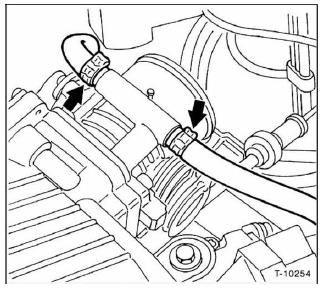
Disconnect the coolant lines from the throttle body connection.
Cut the hose clamps -arrows- with side cutters. Replace them with screw clamps during installation.
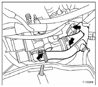
Disconnect the coolant lines from the thermostat (cylinder head) by loosening the hose clamps -arrows-. To prevent the hoses from being swapped during installation, mark the connections and corresponding hoses with a colored pen.
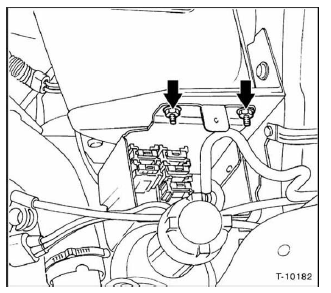
Remove the cover of the fuse and relay box on the battery holder with 1 screw. Unscrew 2 nuts -arrows- and set the box aside.
Remove engine control unit, see page 89.
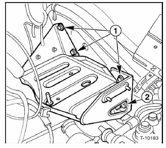
Unscrew battery holder bracket with screws -1- and -2-.
Lift the bracket and unclip the cable holder underneath.
Unhook the accelerator cable from the throttle body connection.
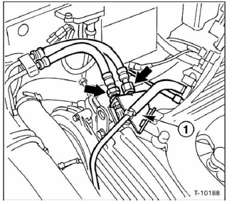
Unscrew the retaining bracket -1- for the fuel lines from the intake manifold.
Unscrew the fuel supply line and return line -arrows-, see illustration. Caution: The fuel system is under pressure. Catch escaping fuel with a thick rag.

Unscrew the oil dipstick tube and filler neck from the intake manifold -arrows-. Disconnect the crankcase breather hose from the filler tube.
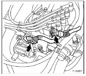
Disconnect the multiple connector for the injectors and ignition coil -arrows-,
Disconnect the connector from the coolant thermostat.
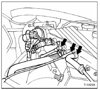
Disconnect the vacuum hoses for fuel vapor, brake booster and pressure sensor from the intake manifold or throttle body section. Before disconnecting, mark hoses and connections with Tesa tape to avoid mix-ups during installation.
Disconnect the connectors for the idle control valve, intake air temperature sensor and throttle position potentiometer, see illustration.
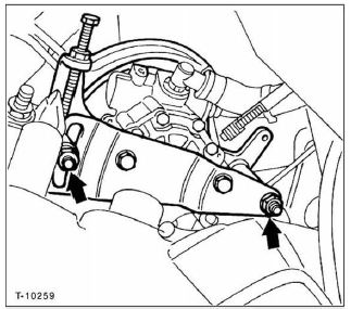
Unscrew the power steering pump -arrows-. Set the pump aside without disconnecting the connected lines.

Unscrew the heat shield from the exhaust manifold -arrows-,
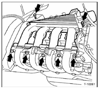
Unscrew the intake manifold from the lower intake manifold and the cylinder head -arrows- and remove it.
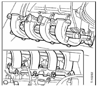
Unscrew the lower intake manifold from the cylinder head. The illustration shows the intake manifold as seen from below.
Remove the timing belt, see page 22.
Unscrew the fuel line bracket with the bolt above the camshaft sprockets.
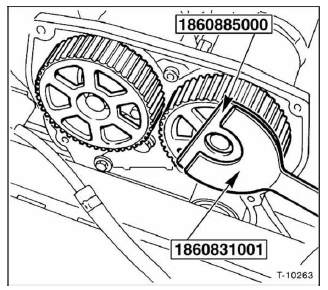
Remove the camshaft sprockets. Lock the camshaft sprocket with a holding tool so the camshaft does not turn. If necessary, make a similar tool yourself, such as the Fiat tool shown.

Unscrew the rear timing belt cover plate from the cylinder head -arrows-.
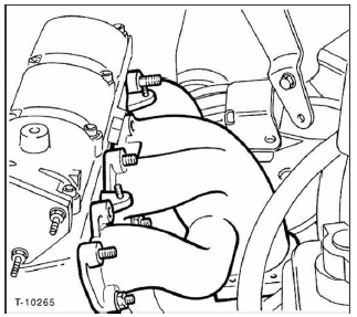
Unscrew the exhaust manifold from the cylinder head.
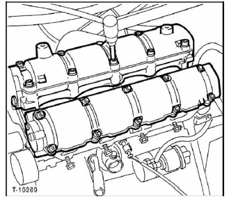
Using a Torx wrench, unscrew both cylinder head covers/camshaft housings in a crisscross pattern and remove them with the gasket.
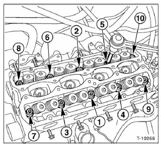
Using a Torx bit, loosen the cylinder head bolts in a crisscross pattern. Caution: Do not remove the bolts fully right away, so the cylinder head does not warp. Loosen all bolts in reverse order of numbering, first by 1/4 turn, then by 1/2 turn.
Lift off the complete cylinder head with intake manifold.
Before installation, clean the gasket residue from the cylinder head and cylinder block using a suitable scraper. Make sure no gasket residue falls into the bores.
If necessary, first close the bores with cloth.
Check the cylinder head and engine block for warpage in longitudinal and transverse directions using a steel straightedge and feeler gauge. If necessary, rework (workshop task). Unevenness must not exceed 0.1 mm.
Check the cylinder head for cracks and the cylinder running surfaces for scoring.
Carefully clean the cylinder head bolt bores of oil and other residue. Caution: There must be no oil in the blind holes, otherwise the bolts will not apply full clamping force to the cylinder head even if tightened to the correct torque. The engine block may also crack.
For cleaning, use compressed air, or wrap a rag around a screwdriver and clean the bores with it.
Cylinder head gasket
Caution: The cylinder head gasket is of the "Astadur" type.
Due to the special properties of the gasket, it polymerizes, i.e. hardens, during later engine operation. For polymerization to occur, the following conditions must be met:Store the gasket in its undamaged original packaging.
Do not remove the gasket from its packaging until shortly before installation.
Do not soil the gasket or wet it with oil.
Clean the engine block and cylinder head gasket surfaces free of oil and grease using a lint-free cloth and solvent (for example denatured alcohol).
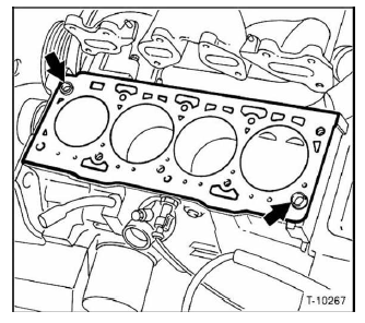
Place the new gasket without sealant so that no bores are covered. The lettering "ALTO" on the cylinder head gasket must face up. Also, make sure both guide bushings -arrows- are correctly seated in the engine block.
Before fitting the cylinder head, check that the camshaft and crankshaft are at TDC. See page 22.
Fit the cylinder head with an assistant.
Always replace the cylinder head bolts during repairs.
Clean the cylinder head bolts and washers and oil them with engine oil. After oiling, let the parts drain for at least 30 minutes.
Insert all cylinder head bolts and tighten them by hand.
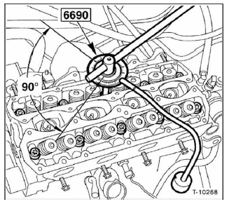
Caution: Tighten the cylinder head bolts with the utmost care. Before tightening the bolts, check the accuracy of the torque wrench. Tightening the cylinder head bolts through the specified angles is made easier with an angle gauge, for example Hazet 6690, see illustration. Note:
If no angle gauge is available, estimate the angle of rotation. To do so, fit a fixed wrench, mark the 90° position on the cylinder head with chalk, and turn the wrench arm up to the mark.

The cylinder head bolts are tightened in 3 stages.
In each stage, tighten the cylinder head bolts in sequence from 1 to 10.
- Stage: with torque wrench 40 N·m
- Stage: turn all bolts a further 90° (1/4 turn) with a fixed wrench
- Stage: turn all bolts a further 90° (1/4 turn) with a fixed wrench
Install the exhaust manifold. Carefully clean the sealing surfaces of soot using a wooden spatula. Place a new gasket between the exhaust manifold and cylinder head.
Use new self-locking special nuts for the exhaust manifold. Tighten the nuts crosswise, first by hand, then in the next pass to 30 N·m.
Screw the heat shield onto the exhaust manifold.
Install the exhaust pipe on the exhaust manifold with a new gasket, see page 121.
Using a crisscross pattern, tighten both cylinder head covers/camshaft housings with a new gasket to 25 N·m.
Screw the rear timing belt cover plate onto the cylinder head.
Tighten the camshaft sprockets to 115 N·m. Lock the camshaft sprocket with the holding tool as during removal so the camshaft does not turn.
Install and tension the timing belt, see page 22.
Fit the intake manifold complete with fuel rail and injectors onto the cylinder head. Insert a new gasket. Tighten the nuts to 30 N·m.
Tighten the intake manifold to the lower intake manifold with new gaskets to 30 N·m. Tighten the intake manifold to the cylinder head with the 2 upper bolts.
Connect the vacuum hoses for fuel vapor, brake booster and pressure sensor to the intake manifold or throttle body section according to the markings.
Connect the connectors for the idle control valve, intake air temperature sensor and throttle position potentiometer, see illustrations under "Removal".
Screw on the power steering pump.
Install the drive belt, see page 58.
Connect the multiple connector for the injectors and ignition coil.
Connect the connector to the coolant thermostat.
Screw the oil dipstick tube and filler neck onto the intake manifold.
Connect the crankcase breather hose to the filler tube.
Screw on the fuel supply line and return line.
Screw the fuel line retaining bracket onto the engine intake manifold.
Hook the accelerator cable onto the throttle body connection.
Fit the battery bracket and bolt it in place.
Bolt the relay box to the battery bracket with 2 nuts.
Place the cover on the relay box and secure it with 1 screw.
Install the engine control unit, see page 89.
Coolant hoses to the thermostat (cylinder head): reconnect according to the marks made during removal and secure with screw clamps.
Connect the coolant hoses to the throttle body connection and secure with screw clamps.
Install the air filter and air hose to the throttle body connection, see page 100.
Refill coolant, see page 71.
Check the engine oil level and top up with oil if necessary.
If the cylinder head was removed due to a defective cylinder head gasket, an early oil change including an oil filter change is recommended, as the engine oil may contain coolant.
Disconnect the negative (-) battery terminal. Set the clock and enter the radio anti-theft code.
Test yourself
A quick Fiat Bravo quiz: every answer comes with an explanation and a link to the manual page.