Removing and Installing Front Door Handle and Lock Cylinder
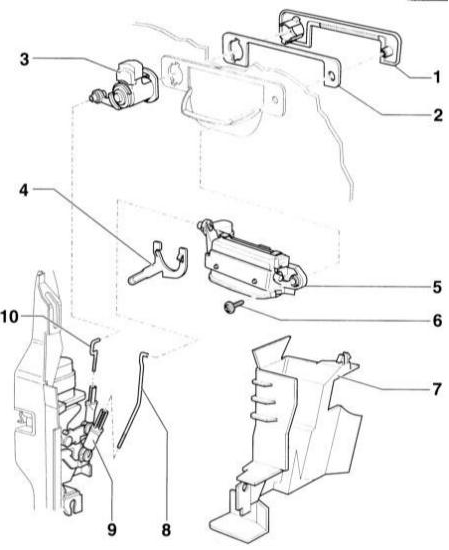 Front Door Handle and Lock Cylinder 1 – visor 2 – pad 3 – lock cylinder 4 – swivel bracket 5 – door handle 6 – screw, 5 N·m 7 – door lock cover 8 – safety rod. To remove, disconnect actuating element –9–. 9 – actuating element 10 – lock cylinder safety rod
CAUTION
The handle shown in the illustration is installed on vehicles with chassis numbers starting from 8L XA 000 001.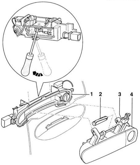 Front Door Handle. Models with chassis numbers starting from 8L XA 000 001 1 – handle base. The lock cylinder is part of the base and cannot be removed separately. 2 – locking pin. When installing, the pin must fully engage the pivot lever. 3 – pivot lever 4 – door handle
CAUTION
Starting from chassis number 8L XA 000 01, a lock and handle of modified design are installed. Removal of the modified handle is described in subsection Removing and Installing Inner Fender Trim. The handle and lock cylinder can be removed separately. To do so, follow the relevant instructions.REMOVAL
PROCEDURE
1. Remove the door adjusting element holder. Refer to subsection Removing and Installing Front Door and Adjusting Element Holder.
2. Disconnect cover –7– and remove it from the bottom of the door lock.
3. Disconnect the locking rod –8– from the handle.
4. Disconnect the locking rod –10– from the lock cylinder –3–.
5. Turn bracket –4– downward (against the direction of travel) and remove the lock cylinder.
6. Unscrew screw –6–.
7. Remove handle cover –1–.
8. Remove the liner –2–.
9. Remove the handle –5– from the inside. INSTALLATION
PROCEDURE
1. Install handle cover –1– with liner –2–.
2. Install door handle –5– from the inside and press it together with the trim panel.
3. Secure the handle with screw –6– at the trim panel.
4. Insert lock cylinder –3– and secure it with bracket –4–. To do this, position the bracket on the lock cylinder and tilt it forward (in the direction of travel).
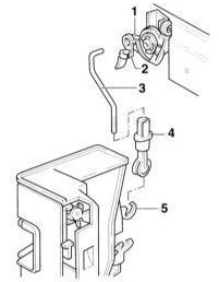
5. Secure the hinge bushing –2– (if removed) in the release lever –1– at the lock cylinder.
6. Connect the lock cylinder locking rod –3– to the hinge bushing –2–.
7. Insert the locking rod –3– into clip –4–.
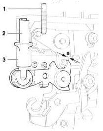
8. Insert the locking rod –1– into clip –2– so that there is a clearance a = 1 mm at lever –4–.
9. After adjusting the clearance, move bushing –3– at clip –2– upward to secure the locking rod.
10. Connect locking rod –8– to handle –5– (refer to illustration Front Door Handle and Lock Cylinder).
11. Install cover –7– from below and secure it from above.
12. Install the adjusting element carrier, refer to sub-section Removing and Installing Front Door and Adjusting Element Carrier. Removing the Handle Trim
PROCEDURE

1. Pull the handle upward.
2. Using a small screwdriver, remove the locking clip from the handle in the direction of the arrow and remove the handle.
3. Pull the handle cover outward.
Models with chassis number starting from 8L XA 000 001 REMOVAL
PROCEDURE
1. Remove the door trim panel and carrier.
2. Remove locking pin –2– and lift hinge lever –3– upward.
3. Using a screwdriver, release the clip at the handle support –1–.
4. Remove the handle support and the lock cylinder with the handle.
INSTALLATION
PROCEDURE
Installation is performed in reverse order.Test yourself
A quick Audi A3 quiz: every answer comes with an explanation and a link to the manual page.