Instrument Cluster Components
Disassembly
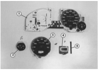
Disassembled instrument cluster, front view
1 – main plate;
2 – temperature gauge;
3 – speedometer;
4 – digital clock;
5 – locating pin.
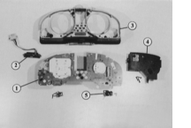
The following components are marked with numbers on the back of the disassembled instrument cluster
1 – main plate with gauges;
2 – indicator unit with outside temperature indicator;
3 – panel;
4 – mini-check system;
5 – instrument illumination control.
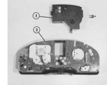
The mini-check system (1) is a separate assembly and is attached to the rear of the instrument cluster (2) with three Phillips-head screws.
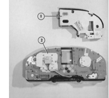
The self-test system (1) is also simply screwed to the rear of the instrument cluster (2). The on-board computer, when equipped, is attached in the same way.
This description applies to the VDO instrument cluster, which is the one most commonly installed on Audi vehicles:
Without disassembling the instrument panel cluster, the following components can be removed from the rear:
Indicators (warning lamps): the incandescent bulbs of the Audi indicators are firmly soldered into their sockets and can only be purchased as a complete unit. When buying a replacement bulb, pay attention to the color of the socket: 1.1-watt, 1.2-watt and 2-watt bulbs are used with differently colored sockets. To remove, turn the socket a quarter turn counterclockwise and pull it out.
Scale illumination: see "Indicators".
Outside air temperature indicator: unscrew the two Phillips-head screws on the indicator unit, then the two more at the connector.
Voltage stabilizer: unscrew one Phillips-head screw, pull the unit out of its connector contacts.
Mini-check system (indicator unit for coolant temperature, brakes and oil pressure): loosen the Phillips-head screws, pull the group instrument out of the connector contacts.
Self-test system: same as the mini-check system.
On-board computer: same as the mini-check system.
Dimmer resistor for scale illumination: unscrew the two hex nuts, remove the dimmer resistor.
After disassembling the instrument cluster (remove the dimmer control for the scale illumination and the self-test or minitest system, or the on-board computer, then remove the 11 combination hex/Torx or Phillips screws from the outside on the back of the unit), the following components become accessible.
Speedometer: remove the four Phillips screws on the back.
Clock with conventional dial: if necessary, remove the coolant temperature gauge (see below), then remove the housing.
Tachometer: remove the three screws on the back of the unit.
Digital clock: remove the tachometer. Remove the two small slotted screws from the digital clock and pull the clock forward. Release the locating pin of the digital clock and carefully remove it.
Fuel gauge or temperature gauge: remove the two hex nuts on the back. Disengage the front part of the housing from the retaining hooks.
Test yourself
A quick Audi 80 quiz: every answer comes with an explanation and a link to the manual page.