Self-Diagnostic System
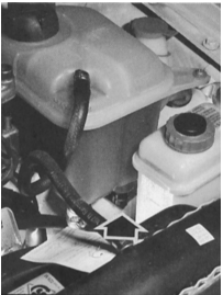
The coolant level sensor (arrow), built into the expansion tank, signals the amount of coolant in the tank.

On vehicles equipped with a self-diagnostic system, similar bulb failure detectors monitor the vehicle lighting. The bulb failure detector for the sedan rear lamps is located on the left side of the luggage compartment. On the Avant (estate) it is located in approximately the same place. The bulb failure detector for the front vehicle lighting is located in the additional relay block under the instrument panel.
As special equipment, Audi offers a self-diagnostic system. It monitors eight functions or operating states after the ignition is switched on and after the low beams or brake light are switched on. Active monitoring also takes place while driving. The self-diagnostic system thus replaces a number of conventional indicators fitted as standard.
The fault indicators, whose display is located in the center of the instrument cluster, are divided into the groups "Danger Warning" and "Caution Warning".
Faults that significantly affect driving safety or may result in serious damage are considered dangerous, and the warning lamps illuminate red. These are the following warnings:
Brake system: brake fluid level too low.
Engine oil pressure: oil pressure at idle drops below 0.3 bar, or at engine speeds above 2100 rpm the values of 1.8 bar (models with 4- and 5-cylinder engines) or 2.5 bar (models with 6-cylinder engines) are not reached.
Coolant: coolant temperature rises above 120°C, or operating temperature is not reached, or coolant level is too low.
In addition to the red warning light from the instrument cluster, a triple buzzer sounds. Warning signals have priority over caution signals. As long as a warning signal is present, the caution signal is suppressed. It appears only after the cause of the warning signal has been eliminated.
Caution signals are displayed on the panel in yellow and are accompanied by a single buzzer tone. These are the following signals:
Brake signal: this symbol appears immediately after the ignition is switched on. If the brake pedal is pressed, the symbol goes out, provided that both brake lights are functioning.
Lighting: the system self-test cannot perform this check fully automatically. The driver must first switch on the low beam. The low beam and tail lights are monitored simultaneously. The system cannot indicate a simultaneous failure of both low beam filaments or both tail light filaments, but this fault is unlikely to occur.
Battery: the battery symbol illuminates if the battery voltage falls outside the specified range of 10.6–15.6 V.
Windshield washer system: this indicator shows that the washer fluid level in the reservoir is too low.
Fuel tank: the refueling symbol illuminates if only 12 L of fuel remains in the fuel tank.
If several faults are present, the caution signals on the warning display light up in turn when the ignition is switched on.
The «OK» signal should appear if, after switching on the ignition and pressing the brake pedal, the «Bremslicht» (brake light) message goes out. «OK» in this case means that all test stages have been passed without fault messages. After a short time the signal goes out.
Bulb failure detectors
These units operate on the electromagnetic principle and compare the current flowing in the wiring, for example, to the left and right low beams. If there is no current draw in one circuit due to an open circuit or a defective bulb, the monitoring unit detects the difference and reports it to the control module. If both bulbs fail, which occurs very rarely, naturally no difference is detected either. In this case the monitoring unit cannot detect the fault.
Note: when connecting the trailer connector, make sure the wires to the tail lights are connected before the bulb failure detector (located at the rear left in the luggage compartment). If power is taken from one of the tail lights, then with the trailer lighting connected, the bulb failure detector receives unaccounted current data in the circuit and reports a «bulb fault».
Removing the control module
The self-test system control module is screwed to the back of the instrument cluster together with the indicator unit. For removal of the self-test module, refer to the «Disassembly» section at the beginning of this chapter.
Troubleshooting the self-test system
Checking the self-test system is only partially possible at home: first check all sensors. If no fault is found here, the fault must be sought in the self-test module.
PROCEDURE
Sensors are checked in the same way as when checking the indicators of the standard instrument panel.
The coolant level sensor, which is fitted only in the self-test system, is checked as follows: if the indicator remains lit although the coolant reservoirs are full, disconnect the cable connectors at the reservoir. If the warning signal now goes out, the sensor is faulty.
The bulb failure detectors for both the front (location: additional relay block on the left under the instrument panel) and the rear (location: left side of the luggage compartment) must be checked by a workshop.
Self-check of the indicator unit
PROCEDURE
With the ignition on and the vehicle stationary (or driving at maximum speed 5 km/h), press the button at the lower left of the instrument cluster.
If the indicators and the system are working properly, all symbol signals should appear in turn on the instrument panel.
This check is not possible if the warning signal is illuminated.
Additional functions on the self-test display
Speed warning: after storing the current driving speed (by pressing the left button on the instrument cluster at the desired speed), the self-test system indicates a significant exceeding of this speed by displaying the symbol and sounding a buzzer. This stored value is retained until the ignition is switched off, unless another driving speed has been stored or the memory has been erased (hold the far left button pressed for one second).
Radio frequency indicator: if the indicator field is not occupied by self-test information, it shows the radio station frequency on car radios so equipped. The indicator display also shows stereo reception or an inserted cassette (Tape). If radio stations transmit radio data system signals, the «RDS» message appears in the indicator field. The radio display can then show the name of the radio station.
Test yourself
A quick Audi 80 quiz: every answer comes with an explanation and a link to the manual page.