Yaw Rate Sensor (C1234,C1472,C1474)
DESCRIPTION
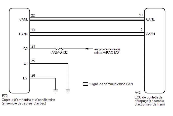
The Skid Control ECU (Brake Actuator Assembly) receives signals from the yaw rate and acceleration sensor (Airbag Sensor Assembly) via the CAN communication system.
HINT:
If a malfunction occurs in the bus lines between the yaw rate and acceleration sensor (airbag sensor assembly) and the CAN communication system, DTC U0123 (Lost Communication with Yaw Rate Sensor Module) is set. When DTC U0123 is set together with DTC C1234, C1472 and/or C1474, check and repair the parts indicated by DTC U0123 first.
These DTCs may be stored under any of the following conditions:
- Yaw rate and acceleration sensor circuit malfunction.
- Yaw rate and acceleration sensor (airbag sensor assembly) installation malfunction
- Yaw rate and acceleration sensor signal malfunction.
DTC No. | Detection Item | DTC Detection Condition | Suspected Area |
|---|---|---|---|
C1234 |
Yaw rate sensor |
One of the following conditions is detected:
|
|
C1472 |
Acceleration Sensor |
One of the following conditions is detected:
|
|
C1474 |
Longitudinal G Sensor |
One of the following conditions is detected:
|
|
Vehicle Operating Conditions |
||||
|---|---|---|---|---|
Sequence 1 | Sequence 2 | Sequence 3 |
||
Diagnostic Condition |
- |
- |
- |
- |
Malfunction Status |
The yaw rate sensor offset value is estimated to be less than -5.25 deg/s or greater than 5.25 deg/s, based on offset correction performed while the vehicle is stopped and the vehicle starts. |
○ |
- |
- |
Offset correction is not completed while the vehicle is stopped, and the yaw rate sensor offset value is estimated to be less than -15 deg/s or greater than 15 deg/s, based on offset correction performed while the vehicle is driving. |
- |
○ |
- |
|
Offset correction completed while the vehicle is stopped, and the yaw rate sensor value is less than -7.5 deg/s or greater than 7.5 deg/s. |
- |
- |
○ |
|
Detection Duration |
- |
- |
- |
|
Number of Trips |
1 trip(s) |
1 trip(s) |
1 trip(s) |
|
HINT:
The DTC is output when the conditions for any one of the sequences in the table above are met.
DTC Detection Conditions: C1234Vehicle Operating Conditions |
||||
|---|---|---|---|---|
Sequence 4 | Sequence 5 | Sequence 6 |
||
Diagnostic Condition |
- |
- |
- |
- |
Malfunction Status |
The yaw rate sensor offset value is estimated to be less than -7.5 deg/s or greater than 7.5 deg/s, based on offset correction performed while the vehicle is driving. |
○ |
- |
- |
After the stability control system is activated, but before the vehicle starts, the yaw rate sensor value is less than -30 deg/s or greater than 30 deg/s for 5 seconds or more while the vehicle is stopped. |
- |
○ |
- |
|
After the stability control system is activated, but before the vehicle starts, the yaw rate sensor value is less than -30 deg/s or greater than 30 deg/s for 0.5 seconds or more when the vehicle starts. |
- |
- |
○ |
|
Detection Duration |
- |
- |
- |
|
Number of Trips |
1 trip(s) |
1 trip(s) |
1 trip(s) |
|
HINT:
The DTC is output when the conditions for any one of the sequences in the table above are met.
DTC Detection Conditions: C1234Vehicle Operating Conditions |
||||
|---|---|---|---|---|
Sequence 7 | Sequence 8 | Sequence 9 |
||
Diagnostic Condition |
- |
- |
- |
- |
Malfunction Status |
The yaw rate sensor value is less than -94.75 deg/s or greater than 94.75 deg/s. |
○ |
- |
- |
The change in yaw rate sensor value within 0.04 seconds is abnormal. |
- |
○ |
- |
|
The value measured by the yaw rate sensor is determined to be abnormal based on the estimate from the skid control ECU (brake actuator assembly). |
- |
- |
○ |
|
Detection Duration |
0.8 seconds minimum |
- |
- |
|
Number of Trips |
1 trip(s) |
1 trip(s) |
1 trip(s) |
|
HINT:
The DTC is output when the conditions for any one of the sequences in the table above are met.
DTC Detection Conditions: C1472Vehicle Operating Conditions |
||||
|---|---|---|---|---|
Sequence 1 | Sequence 2 | Sequence 3 |
||
Diagnostic Condition |
- |
- |
- |
- |
Malfunction Status |
With the vehicle stopped, the internal acceleration value is less than -7 m/s2 or greater than 7 m/s2. |
○ |
- |
- |
The yaw rate sensor offset value is estimated to be less than -2.25 m/s2 or greater than 2.25 m/s2, based on offset correction performed while the vehicle is driving. |
- |
○ |
- |
|
The acceleration sensor value is less than -14.6 m/s2 or greater than 14.6 m/s2. |
- |
- |
○ |
|
Detection Duration |
0.4 seconds minimum |
- |
0.8 seconds minimum |
|
Number of Trips |
1 trip(s) |
1 trip(s) |
1 trip(s) |
|
HINT:
The DTC is output when the conditions for any one of the sequences in the table above are met.
DTC Detection Conditions: C1474Vehicle Operating Conditions |
|||
|---|---|---|---|
Sequence 1 | Sequence 2 |
||
Diagnostic Condition |
- |
- |
- |
Malfunction Status |
The yaw rate sensor offset value is estimated to be less than -2.25 m/s2 or greater than 2.25 m/s2, based on offset correction performed while the vehicle is driving. |
○ |
- |
The acceleration sensor value is less than -14.6 m/s2 or greater than 14.6 m/s2. |
- |
○ |
|
Detection Duration |
- |
3 seconds minimum |
|
Number of Trips |
1 trip(s) |
1 trip(s) |
|
HINT:
The DTC is output when the conditions for any one of the sequences in the table above are met.
WIRING DIAGRAM
PRECAUTION / NOTICE / HINT
NOTICE:
Check the fuses for the circuits related to this system before performing the following procedure.
HINT:
If DTCs U0073, U0123 and/or U0126 are set together with DTCs C1234, C1472 and/or C1474, check and repair the parts indicated by U0073, U0123 and/or U0126 first.
Click here
PROCEDURE
CHECK DTCs
(a) Clear the DTCs.
Click here
(b) Turn the ignition switch OFF.
(c) Start the engine.
(d) Drive the vehicle at a speed of 30 km/h or more, turn the steering wheel and decelerate (depress the brake pedal).
(e) Turn the ignition switch to OFF.
(f) Turn the ignition switch to ON and check that no DTCs related to the CAN communication system are set.
Click here
Result:
Result | Proceed to |
|---|---|
No CAN communication system DTCs are output. |
A |
CAN communication system DTCs are output. |
B |
| B |  |
INSPECT CAN COMMUNICATION SYSTEM |
|

CHECK AIRBAG SENSOR ASSEMBLY INSTALLATION
(a) Turn the ignition switch OFF.
(b) Make sure that the yaw rate and acceleration sensor (airbag sensor assembly) is correctly installed.
Click here
OK:
The airbag sensor assembly is tightened to the specified torque.
The airbag sensor assembly is not tilted.
| NG | |
INSTALL AIRBAG SENSOR ASSEMBLY CORRECTLY |
|
CHECK HARNESS AND CONNECTOR (POWER SOURCE TERMINAL)
(a) Make sure there is no looseness in the lock and connector connection. |
|
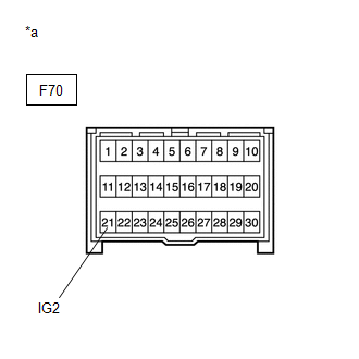
(b) Disconnect the yaw rate sensor (airbag sensor assembly) connector.
(c) Turn the ignition switch to ON.
(d) Measure the voltage according to the value(s) specified in the table below.
Standard voltage:
Tester Connection | Condition | Specified Condition |
|---|---|---|
F70-21 (IG2) - Body Ground |
Ignition Switch in ON position |
11 à 14 V |
| NG | |
REPAIR OR REPLACE WIRE HARNESS OR CONNECTOR (POWER SOURCE CIRCUIT) |
|
CHECK HARNESS AND CONNECTOR (POWER SOURCE TERMINAL)
(a) Turn the ignition switch OFF. |
|
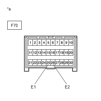
(b) Measure the resistance according to the value(s) in the table below.
Standard resistance:
Tester Connection | Condition | Specified Condition |
|---|---|---|
F70-25 (E1) - Body Ground |
Always |
Below 1 Ω |
F70-26 (E2) - Body Ground |
Always |
Below 1 Ω |
HINT:
If troubleshooting was performed according to the symptom chart, refer to the chart and go to the next step before replacing parts.
Click here
| OK | |
REPLACE AIRBAG SENSOR ASSEMBLY |
| NG | |
REPAIR OR REPLACE WIRE HARNESS OR CONNECTOR (GROUND CIRCUIT) |