VSC OFF switch circuit
DESCRIPTION
The skid control ECU assembly is connected to the combination meter assembly via CAN communication.
Pressing the VSC OFF switch disables TRC control and, if held, disables TRC and VSC control. When TRC and VSC operation is turned off, the TRC OFF message is displayed on the multi-information display and the VSC OFF indicator light comes on.
WIRING DIAGRAM
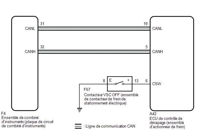
PRECAUTION / NOTICE / HINT
NOTICE:
When replacing the Skid Control ECU (Brake Actuator Assembly), perform system variant coding.
Click here
PROCEDURE
INSPECT CAN COMMUNICATION SYSTEM
(a) Check whether CAN communication system DTCs are output.
Click here
Result:
Result | Proceed to |
|---|---|
No DTCs are output. |
A |
DTCs are output. |
B |
| B |  |
INSPECT CAN COMMUNICATION SYSTEM |
|

CHECK THAT BRAKE ACTUATOR ASSEMBLY CONNECTOR IS PROPERLY CONNECTED
(a) Check that the skid control ECU (brake actuator assembly) connector is properly connected.
OK:
The connector is correctly connected.
| NG | |
CONNECT CONNECTOR TO BRAKE ACTUATOR ASSEMBLY CORRECTLY |
|
READ VALUE USING TECHSTREAM (TRC/VSC OFF MODE)
(a) Select the Data List on the Techstream.
Click here
Tester display | Item | Range | Normal Condition | Diagnostic Note |
|---|---|---|---|---|
TRAC/VSC Off Mode |
TRAC/VSC OFF Mode |
Normal, TRC OFF, VSC Expert mode or VSC OFF |
Normal: Normal mode TRAC OFF: TRAC OFF mode VSC OFF: VSC OFF mode |
- |
TRC/VSC Off Mode
(b) Check whether the indicator and the mode condition on the Techstream change according to VSC OFF switch operation.
Standard:
Switch Operation | Mode condition display | Multi-information Display (TRAC OFF Message) | VSC OFF Warning Light |
|---|---|---|---|
Released |
Normal |
Not displayed |
Not activated |
Press the VSC OFF switch (electric parking brake switch assembly) |
TRC OFF |
Displayed |
Not activated |
Hold the VSC OFF switch (electric parking brake switch assembly) down |
VSC OFF |
Displayed |
Activated |
Result:
Result | Proceed to |
|---|---|
The mode condition and indicator display do not change. |
A |
The mode condition display is normal, but the indicator does not change. |
B |
The indicator and mode condition display operate normally. |
C |
| B | |
CHECK METER / GAUGE SYSTEM |
| C | |
USE SIMULATION METHOD TO CHECK |
|
PERFORM ACTIVE TEST USING TECHSTREAM (TRC OFF INDICATOR AND VSC OFF INDICATOR)
(a) Select the Active Test mode on the Techstream.
Click here
Tester display | Item | Control Range | Diagnostic Note |
|---|---|---|---|
TRC(TRAC) OFF Indicator Light |
Multi-information display (TRC OFF message) |
ON / OFF display |
Inspect the instrument cluster assembly |
VSC OFF Indicator Light |
VSC OFF Warning Light |
Light on / off |
Inspect the instrument cluster assembly |
TRC(TRAC) OFF Indicator Light
Chassis > ABS/VSC/TRAC/EPB > Active TestVSC OFF Indicator Light
(b) Make sure that the multi-information display (TRC OFF message) and the VSC OFF indicator on the combination meter turn on or off depending on Techstream operation.
OK:
The multi-information display (TRC OFF message) and VSC OFF indicator turn on or off according to Techstream operation.
| NG | |
GO TO STEP 7 |
|
INSPECT ELECTRIC PARKING BRAKE SWITCH ASSY
(a) Inspect the electric parking brake switch assembly.
Click here
| NG | |
REPLACE ELECTRIC PARKING BRAKE SWITCH ASSY |
|
INSPECT WIRE HARNESS AND CONNECTOR (BRAKE ACTUATOR ASSEMBLY - ELECTRIC PARKING BRAKE SWITCH ASSEMBLY)
(a) Make sure there is no looseness in the lock and connector connection.
OK:
The connector is correctly connected.
(b) Disconnect the A42 connector from the Skid Control ECU (Brake Actuator Assembly).
(c) Check the connector housing and terminals for deformation and corrosion.
OK:
No deformation or corrosion.
(d) Measure the resistance according to the value(s) in the table below.
Standard resistance:
Tester Connection | Condition | Specified Condition |
|---|---|---|
A42-6 (CSW) - F67-13 (+) |
Always |
Below 1 Ω |
A42-6 (CSW) or F67-13 (+) - Body ground |
Always |
10 kΩ minimum |
F67-8 (E) - Body ground |
Always |
Below 1 Ω |
| OK | |
REPLACE BRAKE ACTUATOR ASSEMBLY |
| NG | |
REPAIR OR REPLACE HARNESS OR CONNECTOR |
CHECK COMBINATION METER ASSEMBLY
(a) Perform the Active Test of the combination meter assembly using the Techstream.
Click here
Meter Display 1
Body Electrical > Combination Meter > Active TestVSC OFF Indicator
(b) Check the combination meter assembly.
OK:
The multi-information display (TRC OFF message) and VSC OFF indicator turn on or off according to Techstream operation.
| OK | |
REPLACE BRAKE ACTUATOR ASSEMBLY |
| NG | |
CHECK METER / GAUGE SYSTEM |