Open in ABS Motor Relay Circuit (C146C)
DESCRIPTION
The ABS motor relay supplies power to the pump motor. While ABS is active, the Skid Control ECU activates the ABS motor relay to operate the pump motor.
If the voltage supplied to the ABS motor relay (+BM) is too low due to low battery or alternator voltage, this DTC may be stored.
DTC No. | Detection Item | DTC Detection Condition | Suspected Area |
|---|---|---|---|
C146C |
Open in ABS Motor Relay Circuit |
One of the following conditions is detected:
|
|
Vehicle Operating Conditions |
||||
|---|---|---|---|---|
Sequence 1 | Sequence 2 | Sequence 3 |
||
Diagnostic Condition |
- |
- |
- |
- |
Malfunction Status |
When the ABS motor relay is activated, no voltage is supplied to the pump motor. |
○ |
- |
- |
When the ABS motor relay is not activated, the pump motor voltage is high. |
- |
○ |
- |
|
The Skid Control ECU determines that the pump motor is not operating normally. |
- |
- |
○ |
|
Detection Duration |
- |
- |
- |
|
Number of Trips |
1 trip(s) |
1 trip(s) |
1 trip(s) |
|
HINT:
The DTC is output when the conditions for any one of the sequences in the table above are met.
WIRING DIAGRAM
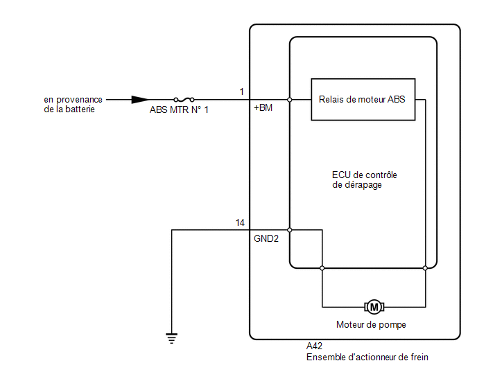
PRECAUTION / NOTICE / HINT
NOTICE:
- When replacing the Skid Control ECU (Brake Actuator Assembly), perform system variant coding.
Click here

- Check the fuses for the circuits related to this system before performing the following procedure.
HINT:
If C1241 and/or C1417 is output together with DTC C146C, first check and repair the components indicated by C1241 and/or C1417.
for C1241: Click here
for C1417: Click here
PROCEDURE
PERFORM ACTIVE TEST USING TECHSTREAM (ABS MOTOR RELAY)
(a) Connect the Techstream to the DLC3.
(b) Start the engine.
(c) Select the Active Test using the Techstream.
Click here
Tester display | Item | Control Range | Diagnostic Note |
|---|---|---|---|
Motor Relay |
ABS Motor Relay |
Relay ON / OFF |
Engine operating noise is audible |
Motor Relay
(d) Check the pump motor operating noise when it is activated using the Techstream.
Result:
Result | Proceed to |
|---|---|
An operating noise is heard. |
A |
No operating noise is heard. |
B |
| B |  |
GO TO STEP 3 |
|

CONFIRM DTC AGAIN
HINT:
This DTC is stored when a malfunction occurs in the Skid Control ECU (Brake Actuator Assembly).
The ABS motor relay is built into the Skid Control ECU (Brake Actuator Assembly).
Under these conditions, it is impossible to check the motor relay and motor relay unit. Be sure to check whether the DTC is output again before replacing the Skid Control ECU (Brake Actuator Assembly).
(a) Turn the ignition switch OFF.
(b) Clear the DTCs.
Click here
(c) Turn the ignition switch to OFF.
(d) Start the engine.
(e) Drive the vehicle at a speed of at least 40 km/h for at least 30 seconds.
(f) Check whether the same DTC is output.
Click here
Result:
Result | Proceed to |
|---|---|
DTC C146C is not output. |
A |
DTC C146C is output. |
B |
HINT:
- When a vehicle speed signal of at least 40 km/h is received by the Skid Control ECU (Brake Actuator Assembly) while the ignition switch is ON, the Skid Control ECU performs a self-diagnosis of the motor circuit.
- If a normal system code is output (no malfunction code is output), lightly shake the connectors, wire harnesses and fuses of the brake actuator assembly.
- If a DTC is output while shaking the connector or wire harness of the Skid Control ECU (Brake Actuator Assembly), check and repair the connector or wire harness.
- If no DTC is output, check for intermittent problems, as the DTC may have been stored due to a poor connection at the connector terminal.
| A | |
USE SIMULATION METHOD TO CHECK |
| B | |
REPLACE BRAKE ACTUATOR ASSEMBLY |
CHECK WIRE HARNESS AND CONNECTOR (+BM TERMINAL)
(a) Make sure there is no looseness in the lock and connector connection. |
|
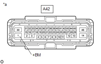
(b) Disconnect the A42 connector from the Skid Control ECU (Brake Actuator Assembly).
(c) Measure the voltage according to the value(s) shown in the table below.
Standard voltage:
Tester Connection | Condition | Specified Condition |
|---|---|---|
A42-1 (+BM) - Body ground |
Always |
11 à 14 V |
| NG | |
REPAIR OR REPLACE WIRE HARNESS OR CONNECTOR (+BM CIRCUIT) |
|
CHECK WIRE HARNESS AND CONNECTOR (GND2 TERMINAL)
(a) Measure the resistance according to the value(s) in the table below. Standard resistance:
|
|
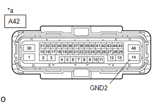
| OK | |
REPLACE BRAKE ACTUATOR ASSEMBLY |
| NG | |
REPAIR OR REPLACE WIRE HARNESS OR CONNECTOR (GND2 CIRCUIT) |