Precautions
PRECAUTION
IGNITION SWITCH TERMS
HINT:
The type of ignition switch used varies depending on vehicle specifications. The terms listed in the table below are used in this section.
Term | Ignition Switch (Position) | Engine Switch (Condition) |
|---|---|---|
Ignition Switch in OFF position |
LOCK |
OFF (Locked) |
Ignition Switch in ACC position |
ACC |
ON (ACC) |
Ignition Switch in ON position |
ON |
ON (IG) |
Starting the engine |
START |
ON (Starting) |
PRECAUTION FOR TROUBLESHOOTING
(a) If a malfunction is caused by a problem at a terminal contact point or by part installation, removing and reinstalling the affected parts may fully or temporarily restore normal system operation.
(b) To determine the malfunctioning area, be sure to check the conditions present when the malfunction occurred, as recorded by the DTCs and freeze frame data, and make a note of this data before disconnecting any connectors or removing and installing any parts.
(c) As the system may be affected by malfunctions in other systems besides the VSC system, be sure to check the DTCs of the other systems.
HANDLING PRECAUTIONS
(a) Do not remove or install VSC parts such as the steering angle sensor or the yaw rate and acceleration sensor (airbag sensor assembly) unless necessary, as they must be properly adjusted after removal and installation.
(b) When performing any work on the VSC system, be sure to carry out the preparation work before and the confirmation work after the work, following the instructions in the repair manual.
(c) Be sure to remove and install the skid control ECU (brake actuator assembly), sensors, etc. with the ignition switch OFF, unless otherwise specified in the inspection procedures.
(d) If the skid control ECU (brake actuator assembly) or a sensor has been removed and installed, it is necessary to check for any system malfunctions after reinstalling the parts. Check the DTCs using the Techstream. Also make sure that the system functions and the signals received by the ECU are normal using the test mode.
PRECAUTIONS FOR DTCs
(a) Warnings for some DTCs cannot be cleared simply by repairing the malfunctioning parts. If the warning is still displayed after repair, the DTC must be cleared after the ignition switch has been turned OFF.
NOTICE:
If a DTC for a malfunctioning part is stored again after being cleared, it means that the DTC has been stored again.
(b) If at least 2 DTCs are output, perform the diagnostic troubleshooting for each DTC one at a time until the problem is identified.
PRECAUTIONS FOR CHASSIS DYNAMOMETER
When using a chassis roller tester such as a speedometer tester, combined speedometer and brake tester, or chassis dynamometer, or when the wheels are turning with the front wheels raised by a jack, perform the following procedure to enter inspection mode and turn off the TRAC and VSC systems.
CAUTION:
- Do not use the roller tester when any of the interlock chains are disconnected.
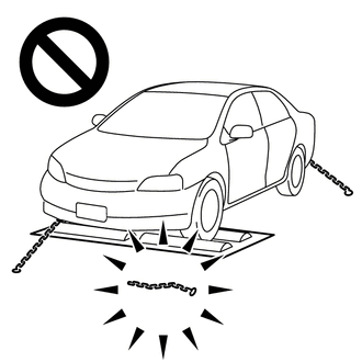
- Using the roller tester with an interlock chain disconnected may cause unexpected vehicle movement.
- Do not use the roller tester when the TRAC or VSC system is able to operate.
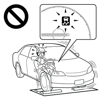
- Operation of the TRAC or VSC system may cause unexpected vehicle movement.
NOTICE:
As a safety precaution, secure the vehicle with tie-down chains.
(a) Entering inspection mode (when using the Techstream)
(1) Make sure the ignition switch is OFF and the engine is stopped.
(2) Make sure the shift lever is in the P position.
(3) Connect the Techstream to the DLC3.
(4) Start the engine.
(5) Turn on the Techstream.
(6) Select the following menus: Chassis / ABS/VSC/TRAC/EPB / Utility / Inspection Mode.
(7) Make sure that the VSC OFF indicator light comes on and the TRC OFF message is displayed on the multi-information display.
HINT:
- If the VSC OFF indicator light does not come on and the TRC OFF message is not displayed on the multi-information display, do not repeat the steps.
- Turning the ignition switch OFF ends inspection mode.
(b) Entering inspection mode (when using the SST check wire)
HINT:
Perform steps "C" to "H" within 30 seconds.
(1) Turn the ignition switch OFF and stop the engine (step "A").
(2) Make sure the shift lever is in the P position (step "B").
(3) Start the engine (step "C").
(4) Apply the parking brake (step "D").
(5) Depress and release the brake pedal twice (step "E").
(6) While depressing the brake pedal, release and apply the parking brake twice (step "F").
(7) With the parking brake applied, depress and release the brake pedal twice (step "G").
(8) Check that the VSC indicator light turns off and the TRAC OFF message is displayed on the multi-information display (step "H").
HINT:
- If the VSC OFF indicator light comes on and the TRC OFF message is displayed on the multi-information display at step "H", repeat steps "A" to "H".
- Turning the ignition switch OFF ends inspection mode.
PRECAUTIONS FOR CAN COMMUNICATION SYSTEM
(a) The CAN communication system is used for communication between the skid control ECU (brake actuator assembly), the steering angle sensor, the yaw rate and acceleration sensor (airbag sensor assembly), and other ECUs. If a malfunction occurs in the CAN communication line, the corresponding DTCs are output.
(b) If any DTC indicating a CAN communication problem is output, repair the malfunction and then troubleshoot the VSC system while communication is normal.
(c) To enable CAN communication, a special type of wiring is used for the CAN communication lines. The wiring used for each communication line consists of a pair of twisted wires of equal length. Do not use a branch wire, as the transmitted data would be altered.