TC and CG terminal circuit
DESCRIPTION
Connecting terminals TC and CG of the DLC3 causes the ECU to display DTCs by flashing the ABS warning light and slip indicator light.
WIRING DIAGRAM
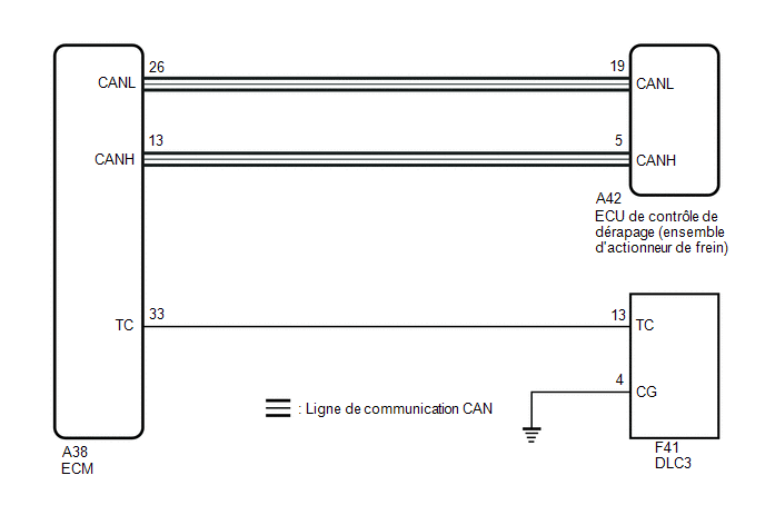
PRECAUTION / NOTICE / HINT
NOTICE:
When replacing the Skid Control ECU (Brake Actuator Assembly), perform system variant coding.
Click here
HINT:
If the warning light continues to flash, there may be a short to ground in the wiring of the DLC3 TC terminal, or an internal short to ground in one or more ECUs.
PROCEDURE
INSPECT CAN COMMUNICATION SYSTEM
(a) Check whether CAN communication system DTCs are output.
Click here
Result:
Result | Proceed to |
|---|---|
No DTCs are output. |
A |
DTCs are output. |
B |
| B |  |
INSPECT CAN COMMUNICATION SYSTEM |
|

CHECK DLC3
(a) Turn the ignition switch to ON.
(b) Measure the voltage according to the value(s) in the table below. Standard voltage:
|
|
| NG | |
GO TO STEP 4 |
|
REPLACE ECM
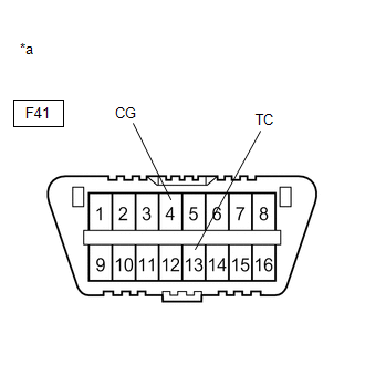
*a |
Front view of DLC3 |
(a) Turn the ignition switch OFF.
(b) Replace the ECM.
Click here
(c) Using SST, connect the TC and CG terminals of the DLC3.
SST: 09843-18040
(d) Make sure the ABS warning light, slip indicator light and Brake Hold Standby Indicator Light flash.
OK:
The ABS warning light, slip indicator light and Brake Hold Standby Indicator Light flash.
HINT:
If troubleshooting was performed according to the symptom chart, refer to the chart and go to the next step before replacing parts.
Click here
| OK | |
END |
| NG | |
REPLACE BRAKE ACTUATOR ASSEMBLY |
CHECK HARNESS AND CONNECTOR (DLC3 TC - ECM)
(a) Turn the ignition switch OFF.
(b) Disconnect the A38 ECM connector.
(c) Measure the resistance according to the value(s) in the table below.
Standard resistance:
Tester Connection | Condition | Specified Condition |
|---|---|---|
F41-13 (TC) - A38-33 (TC) |
Always |
Below 1 Ω |
F41-13 (TC) or A38-33 (TC) - Body Ground |
Always |
10 kΩ minimum |
| NG | |
REPAIR OR REPLACE HARNESS OR CONNECTOR |
|
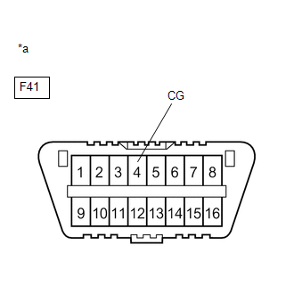
CHECK HARNESS AND CONNECTOR (DLC3 CG - BODY GROUND)
(a) Measure the resistance according to the value(s) in the table below. Standard resistance:
|
|
| NG | |
REPAIR OR REPLACE HARNESS OR CONNECTOR |
|
REPLACE ECM
*a |
Front view of DLC3 |
(a) Replace the ECM.
Click here
(b) Using SST, connect the TC and CG terminals of the DLC3.
SST: 09843-18040
(c) Make sure the ABS warning light, slip indicator light and Brake Hold Standby Indicator Light flash.
OK:
The ABS warning light, slip indicator light and Brake Hold Standby Indicator Light flash.
HINT:
If troubleshooting was performed according to the symptom chart, refer to the chart and go to the next step before replacing parts.
Click here
| OK | |
END |
| NG | |
REPLACE BRAKE ACTUATOR ASSEMBLY |