Brake Hold Standby Light Circuit
DESCRIPTION
When the brake hold switch (electric parking brake switch assembly) is turned on with the ignition switch on, the brake hold standby indicator light comes on when brake hold operation is possible.
WIRING DIAGRAM
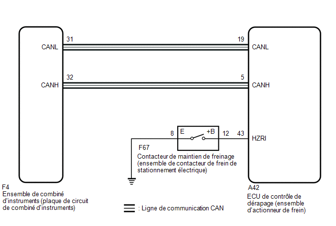
PRECAUTION / NOTICE / HINT
HINT:
When the skid control ECU (brake actuator assembly) is replaced, perform zero point calibration and store the system information.
Click here
PROCEDURE
PRELIMINARY CHECKS
(a) If the brake hold standby indicator light does not come on while the brake hold switch (electric parking brake switch assembly) is pressed, check whether the brake hold function operating conditions are met.
- The driver's door is closed.
- The driver's seat belt is fastened.
- The hood is closed.
- The luggage compartment door is closed.
- The system operates normally.
|

INSPECT CAN COMMUNICATION SYSTEM
(a) Check whether CAN communication system DTCs are output.
Click here
Result:
Result | Proceed to |
|---|---|
No DTCs are output. |
A |
DTCs are output. |
B |
| B |  |
INSPECT CAN COMMUNICATION SYSTEM |
|
CHECK THAT BRAKE ACTUATOR ASSEMBLY CONNECTOR IS PROPERLY CONNECTED
(a) Wiggle the connectors of the skid control ECU (brake actuator assembly) and the wire harnesses vertically and horizontally, and check the Brake Hold Standby Indicator Light condition.
OK:
The connector is correctly connected.
| NG | |
CONNECT CONNECTOR TO BRAKE ACTUATOR ASSEMBLY CORRECTLY |
|
CHECK COMBINATION METER ASSEMBLY
(a) Connect the Techstream to the DLC3.
(b) Turn the ignition switch OFF.
(c) Perform the Active Test of the combination meter assembly using the Techstream.
Click here
Indicat. Brake Hold
(d) Check the combination meter assembly.
OK:
The Brake Hold Standby Indicator Light turns on or off depending on the Techstream operation.
| NG | |
CHECK METER / GAUGE SYSTEM |
|
PERFORM ACTIVE TEST USING TECHSTREAM (BRAKE HOLD STANDBY INDICATOR LIGHT)
(a) Turn the ignition switch to ON.
(b) Select the Active Test mode on the Techstream.
Click here
Tester display | Item | Control Range | Diagnostic Note |
|---|---|---|---|
BH Standby Light |
Brake Hold Standby Light |
Light on / off |
Inspect the combination meter |
(c) Select the Data List on the Techstream.
Click here
Tester display | Item | Range | Normal Condition | Diagnostic Note |
|---|---|---|---|---|
BH Standby Light |
Brake Hold Standby Light |
ON or OFF |
ON: Indicator on OFF: Indicator off |
- |
BH Standby Light
BH Standby Light
(d) Check the operating condition of the Brake Hold Standby Indicator Light when it is activated using the Techstream.
Result:
Result | Proceed to |
|---|---|
The Brake Hold Standby Indicator Light in the Data List does not change when the Active Test is performed. |
A |
The Brake Hold Standby Indicator Light in the Data List is set to ON/OFF using the Active Test. |
B |
| A | |
REPLACE BRAKE ACTUATOR ASSEMBLY |
|
INSPECT ELECTRIC PARKING BRAKE SWITCH ASSY
(a) Inspect the electric parking brake switch assembly.
Click here
| NG | |
REPLACE ELECTRIC PARKING BRAKE SWITCH ASSY |
|
INSPECT WIRE HARNESS AND CONNECTOR (BRAKE ACTUATOR ASSEMBLY - ELECTRIC PARKING BRAKE SWITCH ASSEMBLY)
(a) Disconnect connector A42 from the skid control ECU (brake actuator assembly).
(b) Measure the resistance according to the value(s) in the table below.
Standard resistance:
Tester Connection | Condition | Specified Condition |
|---|---|---|
A42-43 (HZRI) - F67-12 (+B) |
Always |
Below 1 Ω |
A42-43 (HZRI) or F67-12 (+B) - Body ground |
Always |
10 kΩ minimum |
F67-8 (E) - Body ground |
Always |
Below 1 Ω |
| OK | |
REPLACE BRAKE ACTUATOR ASSEMBLY |
| NG | |
REPAIR OR REPLACE HARNESS OR CONNECTOR |