Eco Switch
Components
COMPONENTS
ILLUSTRATION
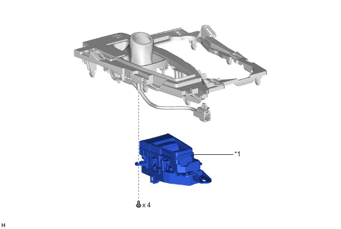
*1 |
ECO SWITCH ASSEMBLY (ELECTRIC PARKING BRAKE SWITCH ASSEMBLY) |
- |
- |
Inspection
INSPECTION
PROCEDURE
1. INSPECT ECO SWITCH ASSEMBLY (ELECTRIC PARKING BRAKE SWITCH ASSEMBLY)
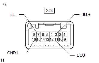
*a |
Component without harness connected (ECO Switch Assembly (Electric Parking Brake Switch Assembly)) |
(a) Measure the resistance according to the value(s) in the table below.
Standard Resistance:
Tester Connection | Switch Condition | Specified Condition |
|---|---|---|
G24-11 (ECU) - G24-16 (GND1) |
ECO switch assembly (electric parking brake switch assembly) off (switch not pressed) |
100 kΩ or higher |
G24-11 (ECU) - G24-16 (GND1) |
ECO switch assembly (electric parking brake switch assembly) on (switch pressed) |
Below 10 Ω |
(b) Check that the switch illuminates.
(1) Battery voltage to the ECO switch assembly (electric parking brake switch assembly) and check that the switch illuminates.
OK:
Tester Connection | Specified Condition |
|---|---|
Battery positive (+) → 3 (ILL+) Battery negative (-) → 7 (ILL-) |
Illuminates |
Installation
INSTALLATION
PROCEDURE
1. INSTALL ECO SWITCH ASSEMBLY (ELECTRIC PARKING BRAKE SWITCH ASSEMBLY)
Click here 
Removal
REMOVAL
PROCEDURE
1. REMOVE ECO SWITCH ASSEMBLY (ELECTRIC PARKING BRAKE SWITCH ASSEMBLY)
Click here 