On-vehicle Inspection. Operating Light Control Rheostat does not Change Light Brightness. Parts Location
On-vehicle Inspection
ON-VEHICLE INSPECTION
PROCEDURE
1. INSPECT COMBINATION METER ASSEMBLY
(a) Inspect speedometer operation
NOTICE:
- The combination meter assembly receives the vehicle speed signal from the skid control ECU (brake actuator assembly) via CAN communication. Therefore, perform the following inspection referring to values on the Data List of the skid control ECU (brake actuator assembly) because it is the source of the vehicle speed signal.
- Data List values of the skid control ECU (brake actuator assembly) are used for this inspection. Therefore, make sure to perform this inspection after confirming that DTCs are not output.
- If the tire size or tire inflation pressure is not within the specified range, or the tires are excessively worn, the speedometer indication error will increase. Therefore, make sure to perform this inspection after checking that the tire size, tire inflation pressure and tire wear are in the specified range.
(1) Warm up the engine.
(2) Connect the Techstream to the DLC3.
(3) Turn the engine switch on (IG).
(4) Turn the Techstream on.
(5) Enter the following menus: Chassis / ABS/VSC/TRAC/EPB / Data List.
(6) Read the Data List according to the display on the Techstream.
Chassis > ABS/VSC/TRAC/EPBTester Display | Measurement Item | Range | Normal Condition | Diagnostic Note |
|---|---|---|---|---|
Vehicle Speed |
Maximum wheel speed sensor |
Min.: 0 km/h, Max.: 326 km/h |
Vehicle stopped: 0 km/h |
When driving at constant speed: No large fluctuations |
Vehicle Speed
Reference mph (for Speedometer with Imperial Units for Main Scale)Techstream Indication (mph) | Acceptable Range (mph) |
|---|---|
20 |
19.2 to 21.7 |
40 |
39.4 to 42.2 |
60 |
59.8 to 62.6 |
80 |
80.0 to 83.2 |
100 |
100.5 to 103.7 |
120 |
120.9 to 124.1 |
140 |
141.3 to 144.5 |
Techstream Indication (km/h) | Acceptable Range (km/h) |
|---|---|
20 |
18.5 to 22.5 |
40 |
38.7 to 43.2 |
60 |
59.2 to 63.7 |
80 |
79.3 to 84.3 |
100 |
99.8 to 104.8 |
120 |
120.3 to 125.3 |
140 |
140.7 to 145.7 |
160 |
161.2 to 166.2 |
180 |
181.6 to 186.6 |
200 |
202.1 to 207.1 |
220 |
222.5 to 227.5 |
240 |
243.0 to 248.0 |
OK:
Speedometer reading is within the acceptable range at each vehicle speed.
(b) Inspect tachometer operation
(1) Warm up the engine.
(2) Connect the Techstream to the DLC3.
(3) Turn the engine switch on (IG).
(4) Enter the following menus: Powertrain / Engine / Data List.
(5) Read the Data List according to the display on the Techstream.
Powertrain > Engine > Data ListTester Display | Measurement Item | Range | Normal Condition | Diagnostic Note |
|---|---|---|---|---|
Engine Speed |
Engine speed |
Min.: 0 rpm, Max.: 16383 rpm |
650 to 750 rpm: Idling (shift lever in N, engine warmed up and A/C off) |
When the crankshaft position sensor is malfunctioning, "Engine Speed" is approximately 0 rpm or varies greatly from the actual engine speed. |
Engine Speed
ReferenceTechstream Indication (rpm) | Acceptable Range (rpm) Data in ( ) is for Reference |
|---|---|
700 |
630 to 770 |
1000 |
(900 to 1100) |
2000 |
(1850 to 2150) |
3000 |
2800 to 3200 |
4000 |
(3800 to 4200) |
5000 |
4800 to 5200 |
6000 |
(5750 to 6250) |
7000 |
6700 to 7300 |
OK:
Tachometer reading is within the acceptable range at each engine speed.
(c) Check LED illumination (LED check)
(1) Check the illumination function of the warning or indicator lights listed below when turning the engine switch on (IG).
OK:
Warning or Indicator Light | Specified Condition |
|---|---|
Brake warning light / red (malfunction) |
Warning or indicator light comes on for about 3 seconds after turning the engine switch on (IG). |
Slip indicator light |
|
VSC OFF indicator light |
|
ABS warning light |
|
Tire pressure warning light |
|
Master warning light |
|
ICS OFF indicator light* |
|
Brake warning light / yellow (minor malfunction) |
|
Brake hold standby indicator light |
|
Brake hold operated indicator light |
|
PCS warning light |
|
SRS warning light |
Warning light comes on for about 6 seconds after turning the engine switch on (IG). |
EPS warning light |
When the engine switch is turned on (IG), warning light (red) illuminates for 2 seconds and then the warning light (yellow) illuminates. |
MIL (Check engine warning light) |
Warning light comes on when the engine switch on (IG). |
- *: w/ Intelligent Clearance Sonar System
Operating Light Control Rheostat does not Change Light Brightness
DESCRIPTION
The combination meter assembly receives signals through this circuit to adjust the illumination of the combination meter assembly. The combination meter assembly sets the illumination level based on the user operation of the light control rheostat switch in the trip switch.
WIRING DIAGRAM
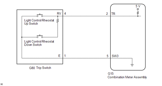
NOTICE:
When replacing the combination meter assembly, always replace it with a new one. If a combination meter assembly which was installed to another vehicle is used, the information stored in it will not match the information from the vehicle and a DTC may be stored.
HINT:
- The illumination level of the combination meter assembly can be adjusted by pressing the light control rheostat switch (trip switch).
- The illumination of the combination meter assembly dims when the taillights are turned on.
- Setting the illumination to maximum brightness cancels the above dimming of the illumination.
PROCEDURE
READ VALUE USING TECHSTREAM
(a) Connect the Techstream to the DLC3.
(b) Turn the engine switch on (IG).
(c) Turn the Techstream on.
(d) Enter the following menus: Body Electrical / Combination Meter / Data List.
(e) Read the Data List according to the display on the Techstream.
Body Electrical > Combination Meter > Data ListTester Display | Measurement Item | Range | Normal Condition | Diagnostic Note |
|---|---|---|---|---|
Light Control Switch (UP) |
Light control rheostat up switch (Trip switch) |
OFF or ON |
OFF: Switch released ON: Switch pushed |
- |
Light Control Switch (DOWN) |
Light control rheostat down switch (Trip switch) |
OFF or ON |
OFF: Switch released ON: Switch pushed |
- |
Tester Display |
|---|
Light Control Switch (UP) |
Light Control Switch (DOWN) |
OK:
Light control rheostat up or down switch (trip switch) condition displayed on the Techstream changes with the actual switch operation.
| OK |  |
REPLACE COMBINATION METER ASSEMBLY |
|

INSPECT TRIP SWITCH
(a) Remove the trip switch.
Click here 
(b) Inspect the trip switch.
Click here
| NG | |
REPLACE TRIP SWITCH |
|
CHECK HARNESS AND CONNECTOR (TRIP SWITCH - COMBINATION METER ASSEMBLY)
(a) Disconnect the G15 combination meter assembly connector.
(b) Measure the resistance according to the value(s) in the table below.
Standard Resistance:
Tester Connection | Condition | Specified Condition |
|---|---|---|
G80-4 (RV) - G15-2 (TR) |
Always |
Below 1 Ω |
G80-1 (E) - G15-5 (SW3) |
Always |
Below 1 Ω |
G80-4 (RV) or G15-2 (TR) - Body ground |
Always |
10 kΩ or higher |
| OK | |
REPLACE COMBINATION METER ASSEMBLY |
| NG | |
REPAIR OR REPLACE HARNESS OR CONNECTOR |
Parts Location
PARTS LOCATION
ILLUSTRATION
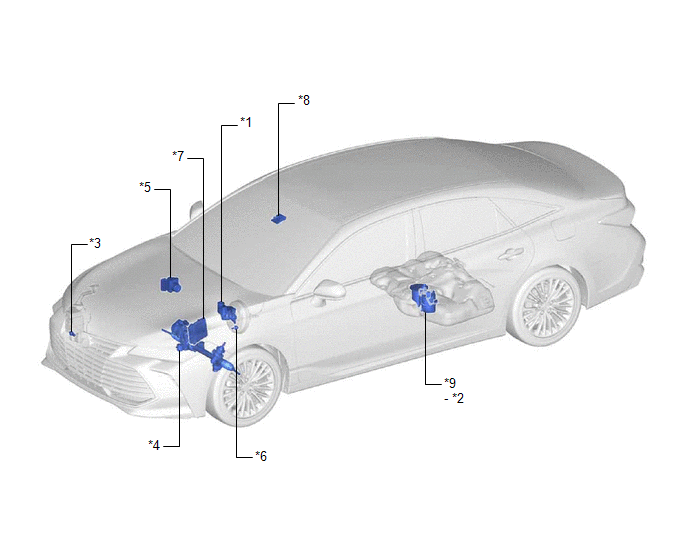
*1 |
BRAKE FLUID LEVEL WARNING SWITCH (BRAKE MASTER CYLINDER RESERVOIR ASSEMBLY) |
*2 |
FUEL SENDER GAUGE ASSEMBLY |
*3 |
LEVEL WARNING SWITCH ASSEMBLY |
*4 |
POWER STEERING ECU (RACK AND PINION POWER STEERING GEAR ASSEMBLY) |
*5 |
SKID CONTROL ECU (BRAKE ACTUATOR ASSEMBLY) |
*6 |
VACUUM WARNING SWITCH |
*7 |
ECM |
*8 |
FORWARD RECOGNITION CAMERA |
*9 |
FUEL SUCTION TUBE WITH PUMP AND GAUGE ASSEMBLY |
- |
- |
ILLUSTRATION
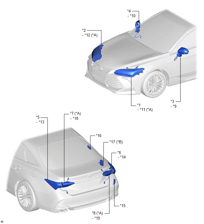
*A |
w/ Cornering Light |
*B |
w/ Adaptive Variable Suspension System |
*1 |
HEADLIGHT ASSEMBLY LH |
*2 |
HEADLIGHT ASSEMBLY RH |
*3 |
OUTER REAR VIEW MIRROR SUB-ASSEMBLY LH |
*4 |
OUTER REAR VIEW MIRROR SUB-ASSEMBLY RH |
*5 |
REAR COMBINATION LIGHT ASSEMBLY LH |
*6 |
REAR COMBINATION LIGHT ASSEMBLY RH |
*7 |
REAR LIGHT ASSEMBLY LH |
*8 |
REAR LIGHT ASSEMBLY RH |
*9 |
SIDE TURN SIGNAL LIGHT ASSEMBLY LH |
*10 |
SIDE TURN SIGNAL LIGHT ASSEMBLY RH |
*11 |
HEADLIGHT ECU SUB-ASSEMBLY LH |
*12 |
HEADLIGHT ECU SUB-ASSEMBLY RH |
*13 |
REAR COMBINATION LIGHT SOCKET AND WIRE LH |
*14 |
REAR COMBINATION LIGHT SOCKET AND WIRE RH |
*15 |
BLIND SPOT MONITOR SENSOR RH |
*16 |
ELECTRICAL KEY AND TIRE PRESSURE WARNING ECU AND RECEIVER |
*17 |
ABSORBER CONTROL ECU |
*18 |
REAR LIGHT CORD LH |
*19 |
REAR LIGHT CORD RH |
- |
- |
ILLUSTRATION
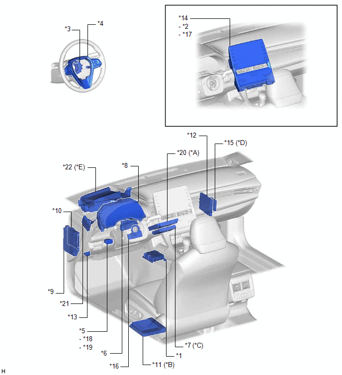
*A |
w/ Navigation System |
*B |
for 14 Speakers |
*C |
w/ Manual (SOS) Switch |
*D |
w/ Intelligent Clearance Sonar System |
*E |
w/ Headup Display System |
- |
- |
*1 |
AIRBAG ECU ASSEMBLY |
*2 |
HAZARD WARNING SWITCH ASSEMBLY |
*3 |
SPIRAL CABLE SUB-ASSEMBLY |
*4 |
STEERING PAD SWITCH ASSEMBLY |
*5 |
TRIP SWITCH |
*6 |
AIR CONDITIONING AMPLIFIER ASSEMBLY |
*7 |
DCM (TELEMATICS TRANSCEIVER) |
*8 |
COMBINATION METER ASSEMBLY |
*9 |
INSTRUMENT PANEL JUNCTION BLOCK ASSEMBLY - ECU-DCC NO. 2 FUSE - METER-IG2 FUSE - HAZ FUSE |
*10 |
MAIN BODY ECU (MULTIPLEX NETWORK BODY ECU) |
*11 |
STEREO COMPONENT AMPLIFIER ASSEMBLY |
*12 |
CERTIFICATION ECU (SMART KEY ECU ASSEMBLY) |
*13 |
DLC3 |
*14 |
RADIO AND DISPLAY RECEIVER ASSEMBLY |
*15 |
CLEARANCE WARNING ECU ASSEMBLY |
*16 |
STEERING SENSOR |
*17 |
REAR SEAT BELT WARNING LIGHT |
*18 |
ODO/TRIP SWITCH |
*19 |
LIGHT CONTROL RHEOSTAT SWITCH |
*20 |
NAVIGATION ECU |
*21 |
DRIVING SUPPORT ECU ASSEMBLY |
*22 |
METER MIRROR SUB-ASSEMBLY |
ILLUSTRATION
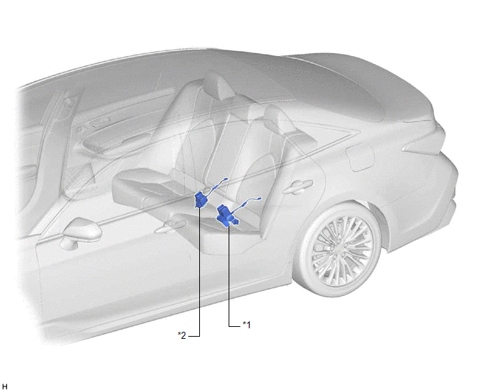
*1 |
REAR SEAT INNER BELT ASSEMBLY LH |
*2 |
REAR SEAT INNER WITH CENTER BELT ASSEMBLY RH |
ILLUSTRATION
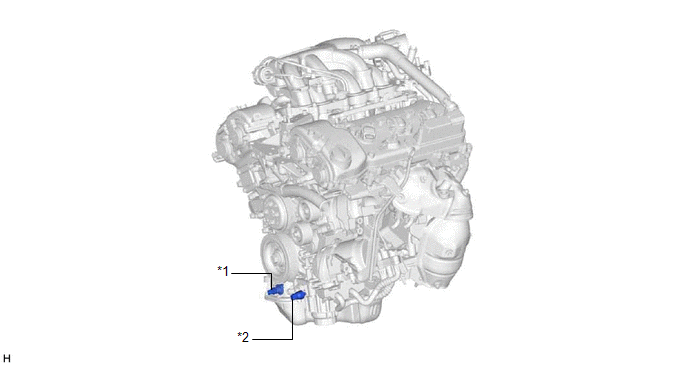
*1 |
ENGINE OIL LEVEL SENSOR |
*2 |
ENGINE OIL PRESSURE SWITCH ASSEMBLY |