Ptc Heater Assembly
Components
COMPONENTS
ILLUSTRATION
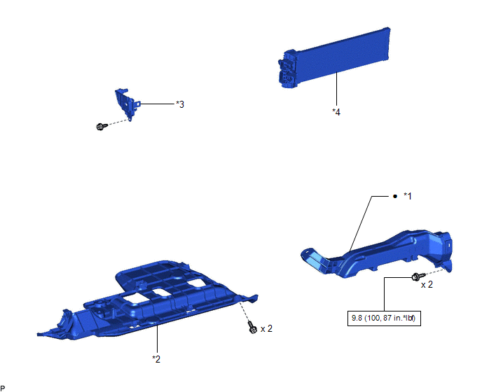
*1 |
NO. 1 AIR DUCT |
*2 |
NO. 1 INSTRUMENT PANEL UNDER COVER SUB-ASSEMBLY |
*3 |
NO. 2 HEATER COVER |
*4 |
QUICK HEATER ASSEMBLY |
 |
N*m (kgf*cm, ft.*lbf): Specified torque |
● |
Non-reusable part |
Inspection
INSPECTION
PROCEDURE
1. INSPECT QUICK HEATER ASSEMBLY
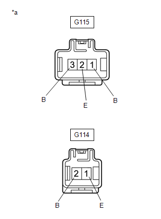
*a |
Component without harness connected (Quick Heater Assembly) |
(a) Measure the resistance according to the value(s) in the table below.
Standard Resistance:
Tester Connection | Condition | Specified Condition |
|---|---|---|
G115-1 (B) - G115-2 (E) |
Always |
10 kΩ or less |
G115-3 (B) - G114-1 (E) |
Always |
10 kΩ or less |
G115-3 (B) - G115-2 (E) |
Always |
10 kΩ or less |
G114-2 (B) - G114-1 (E) |
Always |
10 kΩ or less |
Installation
INSTALLATION
PROCEDURE
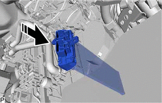
1. INSTALL QUICK HEATER ASSEMBLY
(a) Install the quick heater assembly as shown in the illustration.
 |
Install in this Direction |
2. INSTALL NO. 2 HEATER COVER
(a) Engage the claw and 2 guides.
(b) Install the No. 2 heater cover with the screw.
(c) Engage the clamp.
(d) Connect the 2 connectors.
3. INSTALL NO. 1 AIR DUCT
for Manual Tilt and Manual Telescopic Steering Column:
Click here 
for Power Tilt and Power Telescopic Steering Column:
Click here
4. INSTALL NO. 1 INSTRUMENT PANEL UNDER COVER SUB-ASSEMBLY
Click here
Removal
REMOVAL
PROCEDURE
1. REMOVE NO. 1 INSTRUMENT PANEL UNDER COVER SUB-ASSEMBLY
Click here 
2. REMOVE NO. 1 AIR DUCT
for Manual Tilt and Manual Telescopic Steering Column:
Click here
for Power Tilt and Power Telescopic Steering Column:
Click here
3. REMOVE NO. 2 HEATER COVER
(a) Disconnect the 2 connectors. |
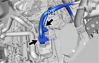 |
(b) Disengage the clamp.
(c) Remove the screw. |
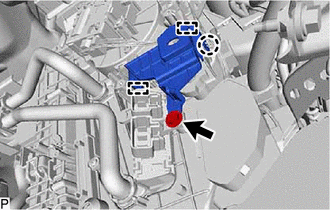 |
(d) Disengage the claw and 2 guides to remove the No. 2 heater cover.
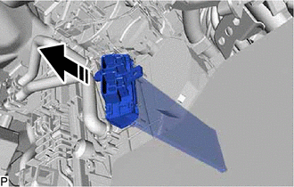
4. REMOVE QUICK HEATER ASSEMBLY
(a) Remove the quick heater assembly as shown in the illustration.
 |
Remove in this Direction |