Headup Display
Components
COMPONENTS
ILLUSTRATION
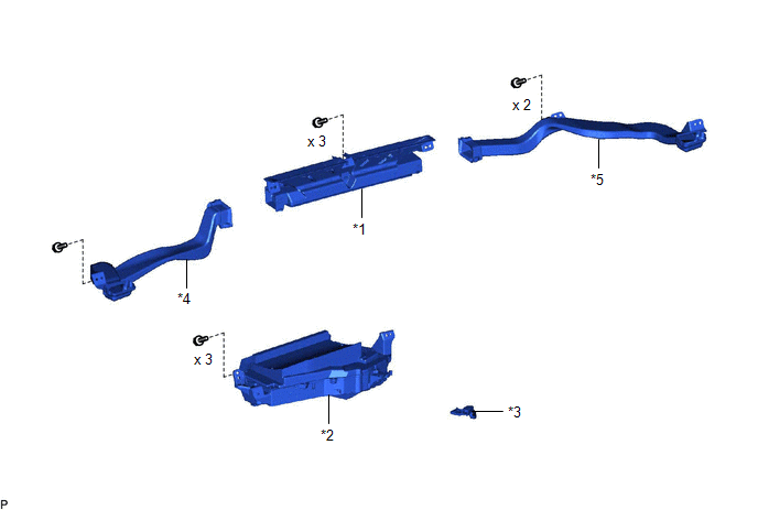
*1 |
DEFROSTER NOZZLE ASSEMBLY |
*2 |
METER MIRROR SUB-ASSEMBLY |
*3 |
METER MIRROR WIRE |
*4 |
NO. 1 SIDE DEFROSTER NOZZLE DUCT |
*5 |
NO. 2 SIDE DEFROSTER NOZZLE DUCT |
- |
- |
Installation
INSTALLATION
PROCEDURE
1. INSTALL METER MIRROR WIRE
(a) Engage the clamp and claw.
(b) Connect the connector to install the meter mirror wire.
2. INSTALL METER MIRROR SUB-ASSEMBLY
(a) Install the meter mirror sub-assembly with the 3 screws.
3. INSTALL DEFROSTER NOZZLE ASSEMBLY
Click here 
4. INSTALL NO. 2 SIDE DEFROSTER NOZZLE DUCT
Click here
5. INSTALL NO. 1 SIDE DEFROSTER NOZZLE DUCT
Click here
6. INSTALL INSTRUMENT PANEL SAFETY PAD SUB-ASSEMBLY
Click here
Removal
REMOVAL
The necessary procedures (adjustment, calibration, initialization or registration) that must be performed after parts are removed and installed, or replaced during headup display (meter mirror sub-assembly) removal/installation are shown below.
Necessary Procedure After Parts Removed/Installed/Replaced (for Gasoline Model)Replaced Part or Performed Procedure | Necessary Procedure | Effect/Inoperative Function When Necessary Procedures are not Performed | Link |
|---|---|---|---|
| *: When performing learning using the Techstream. Click here |
|||
Disconnect cable from negative (-) battery terminal |
Perform steering sensor zero point calibration |
Lane Departure Alert System (w/ Steering Control) |
 |
Pre-collision System |
|||
Intelligent Clearance Sonar System* |
|||
Lighting System (for Gasoline Model with Cornering Light) |
|||
Memorize steering angle neutral point |
Parking Assist Monitor System |
|
|
Panoramic View Monitor System |
|
||
Replaced Part or Performed Procedure | Necessary Procedure | Effect/Inoperative Function When Necessary Procedures are not Performed | Link |
|---|---|---|---|
| *: When performing learning using the Techstream. Click here |
|||
Disconnect cable from negative (-) auxiliary battery terminal |
Perform steering sensor zero point calibration |
Lane Departure Alert System (w/ Steering Control) |
|
Pre-collision System |
|||
Intelligent Clearance Sonar System* |
|||
Lighting System (for HV Model with Cornering Light) |
|||
Memorize steering angle neutral point |
Parking Assist Monitor System |
|
|
Panoramic View Monitor System |
|
||
CAUTION:
Be sure to read Precaution thoroughly before servicing.
for Gasoline Model: Click here
for HV Model: Click here
PROCEDURE
1. REMOVE INSTRUMENT PANEL SAFETY PAD SUB-ASSEMBLY
Click here
2. REMOVE NO. 1 SIDE DEFROSTER NOZZLE DUCT
Click here
3. REMOVE NO. 2 SIDE DEFROSTER NOZZLE DUCT
Click here
4. REMOVE DEFROSTER NOZZLE ASSEMBLY
Click here
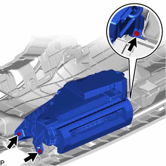
5. REMOVE METER MIRROR SUB-ASSEMBLY
(a) Remove the 3 screws and meter mirror sub-assembly. |
 |
6. REMOVE METER MIRROR WIRE
(a) Disconnect the connector. |
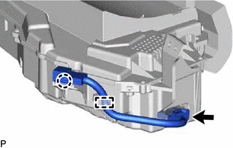 |
(b) Disengage the claw and clamp to remove the meter mirror wire.