How To Proceed With Troubleshooting. Initialization. Odo/Trip Switch Malfunction
How To Proceed With Troubleshooting
HINT:
- Use the following procedure to troubleshoot the meter / gauge system.
- *: Use the Techstream.
PROCEDURE
VEHICLE BROUGHT TO WORKSHOP
|

CUSTOMER PROBLEM ANALYSIS
HINT:
- In troubleshooting, confirm that the problem symptoms have been accurately identified. Preconceptions should be discarded in order to make an accurate judgment. To clearly understand what the problem symptoms are, it is extremely important to ask the customer about the problem and the conditions at the time the malfunction occurred.
- Gather as much information as possible for reference. Past problems that seem unrelated may also help in some cases.
- The following 5 items are important points for problem analysis:
What
Vehicle model, system name
When
Date, time, occurrence frequency
Where
Road conditions
Under what conditions?
Driving conditions, weather conditions
How did it happen?
Problem symptoms
|
INSPECT BATTERY VOLTAGE
(a) Measure the battery voltage.
Standard Voltage:
11 to 14 V
If the voltage is below 11 V, recharge or replace the battery before proceeding to the next step.
(b) Check the fuses and relays.
(c) Check the connector connections and terminals to make sure that there are no abnormalities such as loose connections, deformation, etc.
|
CHECK CAN COMMUNICATION SYSTEM*
(a) Using the Techstream, check for CAN communication system DTCs.
Click here 
Result | Proceed to |
|---|---|
CAN DTCs are not output |
A |
CAN DTCs are output |
B |
| B |  |
GO TO CAN COMMUNICATION SYSTEM |
|
CHECK FOR DTC* (METER / GAUGE SYSTEM)
(a) Check for DTCs.
Body Electrical > Combination Meter > Trouble CodesResult | Proceed to |
|---|---|
DTCs are not output |
A |
DTCs are output |
B |
| B | |
GO TO DIAGNOSTIC TROUBLE CODE CHART |
|
PROBLEM SYMPTOM CONFIRMATION
|
SYMPTOM SIMULATION
|
PROBLEM SYMPTOMS TABLE
(a) Refer to Problem Symptoms Table.
Click here
Result | Proceed to |
|---|---|
Fault is not listed in Problem Symptoms Table |
A |
Fault is listed in Problem Symptoms Table |
B |
| B | |
GO TO PROBLEM SYMPTOMS TABLE |
|
OVERALL ANALYSIS AND TROUBLESHOOTING*
(a) Terminals of ECU.
Click here
(b) Data List / Active Test.
Click here
(c) On-vehicle Inspection.
Click here
(d) Inspection.
|
CIRCUIT INSPECTION
|
ADJUST, REPAIR OR REPLACE
|
CONFIRMATION TEST
| NEXT | |
END |
Initialization
INITIALIZATION
MAINTENANCE REQUIRED REMINDER RESET PROCEDURE
(a) Perform initialization using the multi-information display.
(1) Turn the engine switch on (IG).
(2) Enter the following menus: Settings / Vehicle Settings / Scheduled Maintenance.
(3) Perform initialization according to the multi-information display.
Odo/Trip Switch Malfunction
DESCRIPTION
In this circuit, the combination meter assembly detects ODO/TRIP switch (trip switch) signals via a direct line.
WIRING DIAGRAM
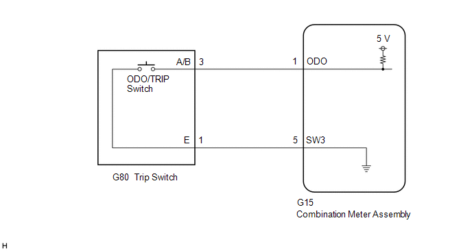
NOTICE:
When replacing the combination meter assembly, always replace it with a new one. If a combination meter assembly which was installed to another vehicle is used, the information stored in it will not match the information from the vehicle and a DTC may be stored.
PROCEDURE
READ VALUE USING TECHSTREAM
(a) Connect the Techstream to the DLC3.
(b) Turn the engine switch on (IG).
(c) Turn the Techstream on.
(d) Enter the following menus: Body Electrical / Combination Meter / Data List.
(e) Read the Data List according to the display on the Techstream.
Body Electrical > Combination Meter > Data ListTester Display | Measurement Item | Range | Normal Condition | Diagnostic Note |
|---|---|---|---|---|
ODO/TRIP Change Switch |
ODO/TRIP switch (Trip switch) |
OFF or ON |
OFF: Switch released ON: Switch pushed |
- |
ODO/TRIP Change Switch
OK:
ODO/TRIP switch (trip switch) condition displayed on the Techstream changes with the actual switch operation.
| OK |  |
REPLACE COMBINATION METER ASSEMBLY |
|

INSPECT TRIP SWITCH
(a) Remove the trip switch.
Click here 
(b) Inspect the trip switch.
Click here
| NG | |
REPLACE TRIP SWITCH |
|
CHECK HARNESS AND CONNECTOR (TRIP SWITCH - COMBINATION METER ASSEMBLY)
(a) Disconnect the G15 combination meter assembly connector.
(b) Measure the resistance according to the value(s) in the table below.
Standard Resistance:
Tester Connection | Condition | Specified Condition |
|---|---|---|
G80-3 (A/B) - G15-1 (ODO) |
Always |
Below 1 Ω |
G80-1 (E) - G15-5 (SW3) |
Always |
Below 1 Ω |
G80-3 (A/B) or G15-1 (ODO) - Body ground |
Always |
10 kΩ or higher |
| OK | |
REPLACE COMBINATION METER ASSEMBLY |
| NG | |
REPAIR OR REPLACE HARNESS OR CONNECTOR |