System Diagram. Tachometer Malfunction. Terminals Of Ecu
System Diagram
SYSTEM DIAGRAM
HINT:
Refer to System Diagram of CAN Communication System.
Click here 
COMBINATION METER ASSEMBLY DIAGRAM
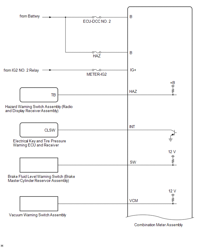
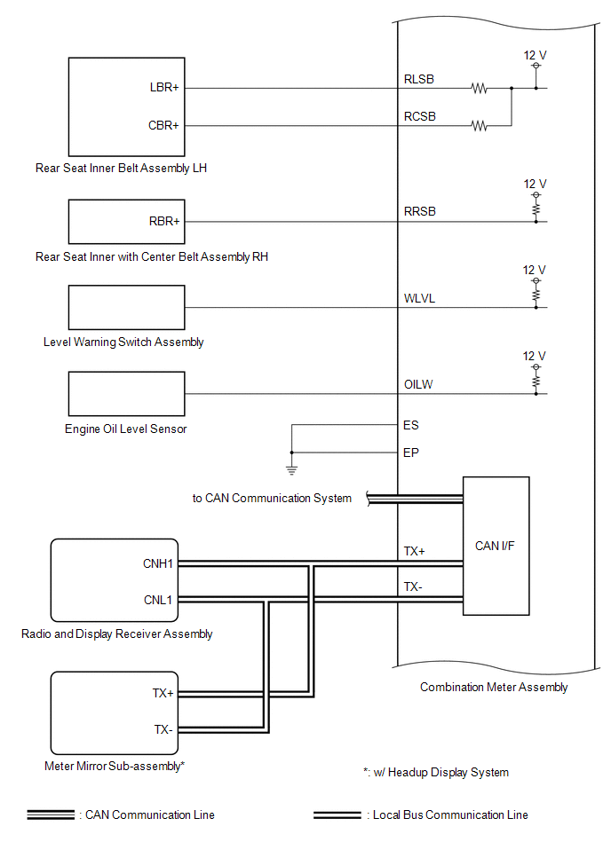
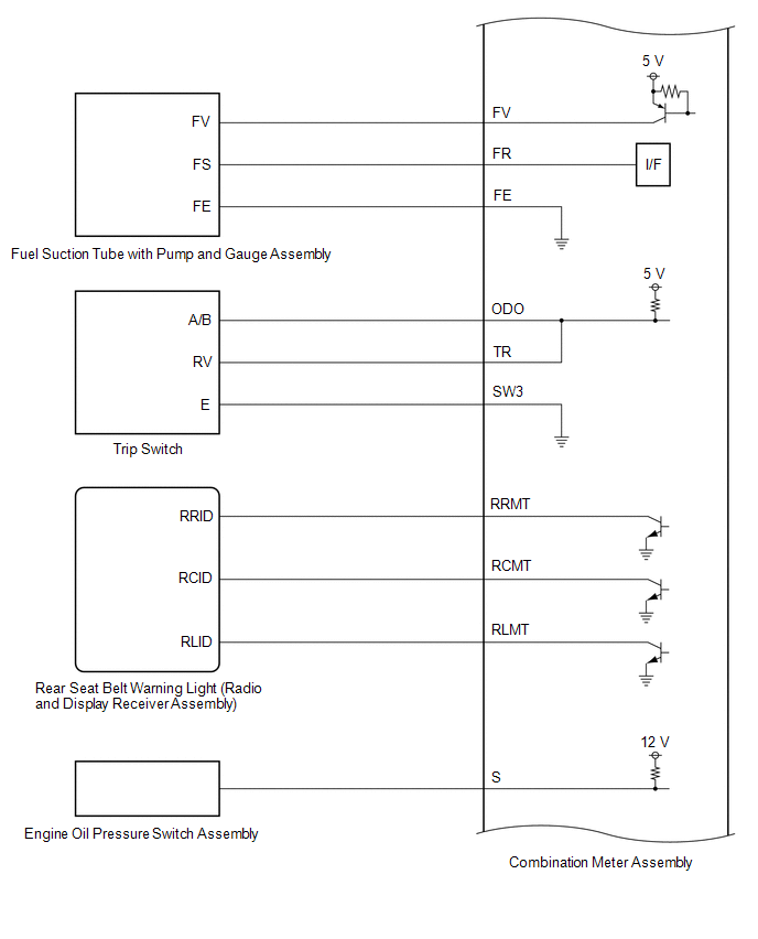
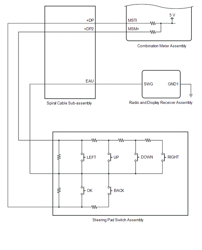
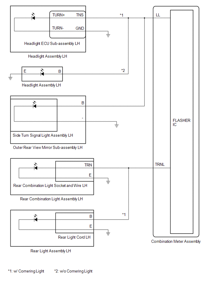
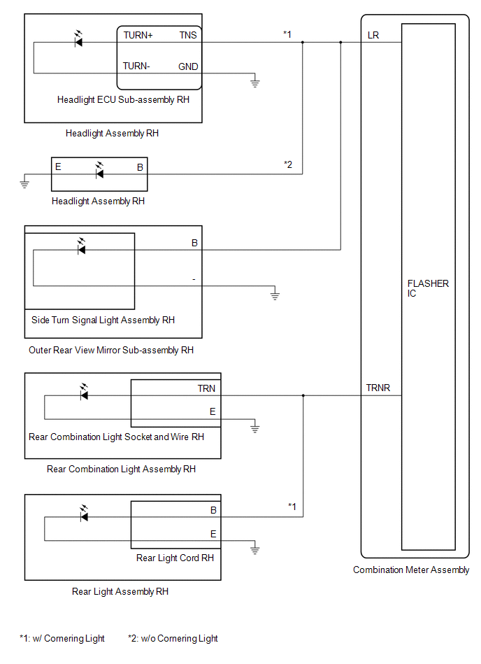
TURN SIGNAL LIGHT DIAGRAM
(a) LH Side
(b) RH Side
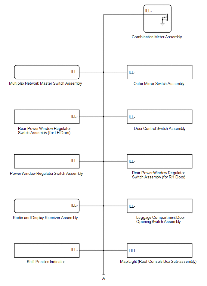
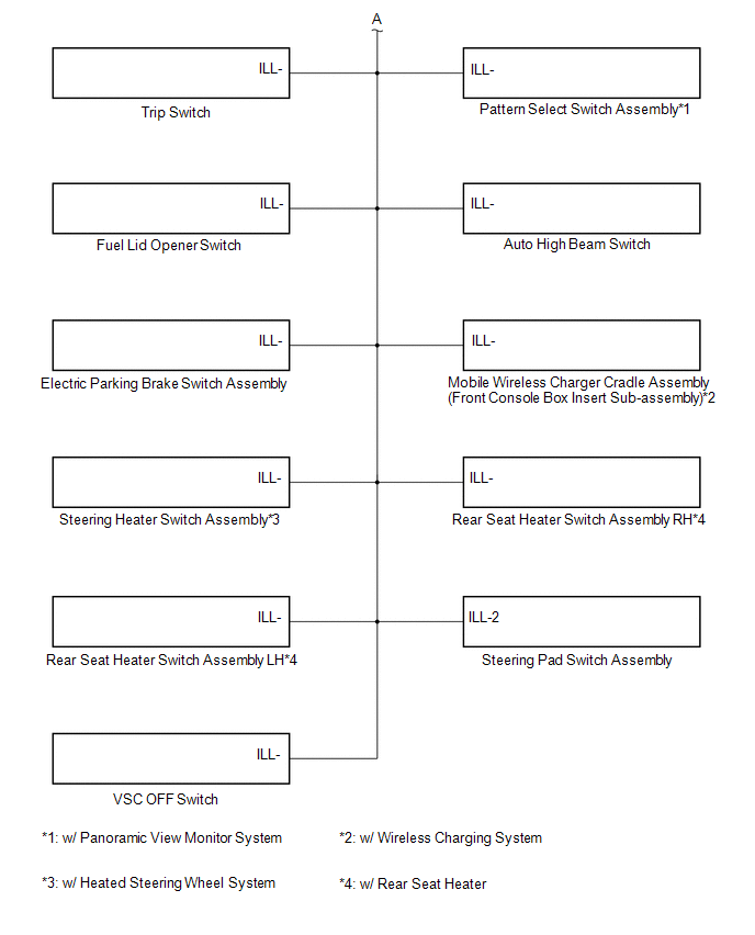
ILLUMINATION DIAGRAM
SPEED SIGNAL DIAGRAM
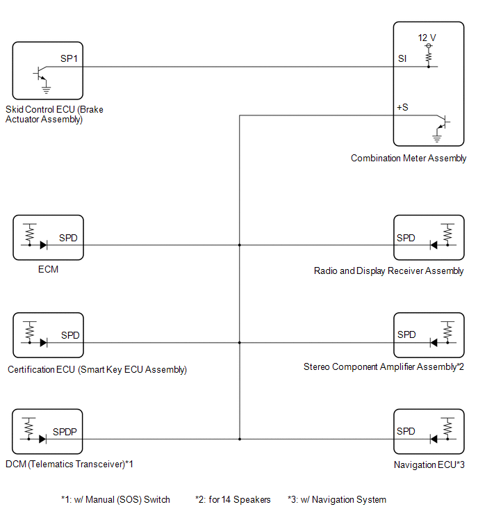
Tachometer Malfunction
DESCRIPTION
In this circuit, the combination meter assembly receives engine speed signals from the ECM via CAN communication. The combination meter assembly displays the engine speed calculated based on the data received from the ECM.
WIRING DIAGRAM
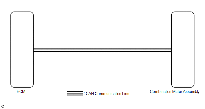
NOTICE:
- When replacing the combination meter assembly, always replace it with a new one. If a combination meter assembly which was installed to another vehicle is used, the information stored in it will not match the information from the vehicle and a DTC may be stored.
- Before replacing the ECM, refer to Registration.
Click here

PROCEDURE
CHECK CAN COMMUNICATION SYSTEM
(a) Check if CAN communication DTCs are output.
Click here
Result | Proceed to |
|---|---|
CAN communication DTCs are not output |
A |
CAN communication DTCs are output |
B |
| B |  |
GO TO CAN COMMUNICATION SYSTEM |
|

CHECK FOR DTC (SFI SYSTEM)
(a) Check if SFI system DTCs are output.
Powertrain > Engine > Trouble CodesResult | Proceed to |
|---|---|
DTCs are not output |
A |
DTCs are output |
B |
| B | |
GO TO SFI SYSTEM |
|
PERFORM ACTIVE TEST USING TECHSTREAM
(a) Connect the Techstream to the DLC3.
(b) Turn the engine switch on (IG).
(c) Turn the Techstream on.
(d) Enter the following menus: Body Electrical / Combination Meter / Active Test.
(e) Perform the Active Test according to the display on the Techstream.
Body Electrical > Combination Meter > Active TestTester Display | Measurement Item | Control Range | Diagnostic Note |
|---|---|---|---|
TachoMeter Operation (0rpm) |
Tachometer (0 rpm) |
ON |
- |
TachoMeter Operation (1000rpm) |
Tachometer (1000 rpm) |
ON |
- |
TachoMeter Operation (2000rpm) |
Tachometer (2000 rpm) |
ON |
- |
TachoMeter Operation (3000rpm) |
Tachometer (3000 rpm) |
ON |
- |
TachoMeter Operation (4000rpm) |
Tachometer (4000 rpm) |
ON |
- |
TachoMeter Operation (5000rpm) |
Tachometer (5000 rpm) |
ON |
- |
TachoMeter Operation (6000rpm) |
Tachometer (6000 rpm) |
ON |
- |
TachoMeter Operation (7000rpm) |
Tachometer (7000 rpm) |
ON |
- |
TachoMeter Operation (0rpm)
Body Electrical > Combination Meter > Active TestTachoMeter Operation (1000rpm)
Body Electrical > Combination Meter > Active TestTachoMeter Operation (2000rpm)
Body Electrical > Combination Meter > Active TestTachoMeter Operation (3000rpm)
Body Electrical > Combination Meter > Active TestTachoMeter Operation (4000rpm)
Body Electrical > Combination Meter > Active TestTachoMeter Operation (5000rpm)
Body Electrical > Combination Meter > Active TestTachoMeter Operation (6000rpm)
Body Electrical > Combination Meter > Active TestTachoMeter Operation (7000rpm)
OK:
Tachometer indication is normal.
| OK | |
REPLACE ECM |
| NG | |
REPLACE COMBINATION METER ASSEMBLY |
Terminals Of Ecu
TERMINALS OF ECU
COMBINATION METER ASSEMBLY
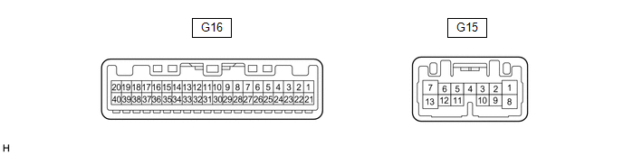
(a) Measure the voltage and resistance and check for pulses according to the value(s) in the table below.
Terminal No. (Symbol) | Wiring Color | Terminal Description | Signal Input/Output | Condition | Specified Condition |
|---|---|---|---|---|---|
G16-1 (ILL-) - Body ground |
LA-L - Body ground |
Illumination signal |
Output |
Taillights off → Taillights on |
Below 1 V → Pulse generation |
G16-2 (EP) - Body ground |
W-B - Body ground |
Ground |
- |
Always |
Below 1 Ω |
G16-4 (INT) - Body ground |
L - Body ground |
Tire pressure warning ECU and receiver signal |
Output |
|
Below 1.5 V → 8 to 15 V |
G16-5 (SI) - Body ground |
W - Body ground |
Speed signal for other systems (Input) |
Input |
Engine switch on (IG), wheel being rotated |
Pulse generation (See waveform 1) |
G16-6 (+S) - Body ground |
L - Body ground |
Speed signal for other systems (Output) |
Output |
Engine switch on (IG), wheel being rotated |
Pulse generation (See waveform 1) |
G16-7 (VCM) - Body ground |
BE - Body ground |
Vacuum warning switch signal |
Input |
Engine started, vacuum warning switch off (brake warning light off) → Vacuum warning switch on (brake warning light on) |
11 to 14 V → Below 1 V |
G16-9 (S) - Body ground |
LA-R - Body ground |
Engine oil pressure signal |
Input |
Engine not started → Engine started |
Below 1 V → 11 to 14 V |
G16-12 (SW) - Body ground |
G - Body ground |
Brake fluid level signal |
Input |
Engine switch on (IG), brake fluid level not low (brake warning light off) → Brake fluid level low (brake warning light on) |
11 to 14 V → Below 1 V |
G16-14 (FR) - G16-33 (FE) |
LG - BE |
Fuel level signal |
Input |
Engine switch on (IG), fuel level full → Fuel level low (fuel level warning light on) |
Pulse generation (See waveform 2) |
G16-15 (FV) - Body ground |
GR - Body ground |
Fuel sender gauge (Power source) |
- |
Engine switch on (IG) |
Pulse generation (See waveform 3) |
G16-17 (WLVL) - Body ground |
LG - Body ground |
Washer fluid level signal |
Input |
Engine switch on (IG), washer fluid level not low → Washer fluid level low |
11 to 14 V → Below 1 V |
G16-18 (RLMT) -Body ground |
BE - Body ground |
Rear seat belt warning light LH signal |
Output |
Engine switch on (IG), rear seat belt warning light LH (radio and display receiver assembly) off → Rear seat belt warning light LH (radio and display receiver assembly) on |
11 to 14 V → Below 1 V |
G16-19 (RCMT) -Body ground |
R - Body ground |
Rear seat belt warning light center signal |
Output |
Engine switch on (IG), rear seat belt warning light center (radio and display receiver assembly) off → Rear seat belt warning light center (radio and display receiver assembly) on |
11 to 14 V → Below 1 V |
G16-20 (RRMT) -Body ground |
G - Body ground |
Rear seat belt warning light RH signal |
Output |
Engine switch on (IG), rear seat belt warning light RH (radio and display receiver assembly) off → Rear seat belt warning light RH (radio and display receiver assembly) on |
11 to 14 V → Below 1 V |
G16-21 (ES) - Body ground |
W-B - Body ground |
Ground |
- |
Always |
Below 1 Ω |
G16-24 (RLSB) - Body ground |
SB - Body ground |
Rear seat belt buckle switch LH signal |
Input |
Engine switch on (IG), rear seat belt LH unfastened → Fastened |
Below 1 V → 11 to 14 V |
G16-25 (RCSB) - Body ground |
B - Body ground |
Rear seat belt buckle switch center signal |
Input |
Engine switch on (IG), rear seat belt center unfastened → Fastened |
Below 1 V → 11 to 14 V |
G16-26 (RRSB) - Body ground |
LG - Body ground |
Rear seat belt buckle switch RH signal |
Input |
Engine switch on (IG), rear seat belt RH unfastened → Fastened |
Below 1 V → 11 to 14 V |
G16-27 (OILW) - Body ground |
W - Body ground |
Engine oil level signal |
Input |
Engine switch on (IG), engine oil level not low → Engine oil level low |
Below 1 V → 11 to 14 V |
G16-28 (MSM+) - Body ground |
GR - Body ground |
Steering pad switch assembly signal |
Input |
Engine switch on (IG), up, down, right and left switches on steering pad switch assembly not pushed |
4.8 to 5.2 V |
G16-29 (MSTI) - Body ground |
R - Body ground |
Steering pad switch assembly signal |
Input |
Engine switch on (IG), OK and back switches on steering pad switch assembly not pushed |
4.8 to 5.2 V |
G16-31 (CANL) |
W |
CAN communication line |
Input/Output |
- |
- |
G16-32 (CANH) |
B |
CAN communication line |
Input/Output |
- |
- |
G16-36 (TX+) |
G |
Local bus communication line |
Input/Output |
- |
- |
G16-37 (TX-) |
W |
Local bus communication line |
Input/Output |
- |
- |
G16-39 (IG+) - Body ground |
GR - Body ground |
Engine switch signal |
- |
Engine switch off → Engine switch on (IG) |
Below 1 V → 11 to 14 V |
G16-40 (B) - Body ground |
LA-B - Body ground |
Battery |
- |
Always |
11 to 14 V |
G15-1 (ODO) - Body ground |
LA-L - Body ground |
ODO/TRIP switch signal |
Input |
Engine switch on (IG), ODO/TRIP switch (trip switch) not pushed |
4.8 to 5.2 V |
G15-2 (TR) - Body ground |
L - Body ground |
Light control rheostat switch signal |
Input |
Engine switch on (IG), light control rheostat up switch (trip switch) and light control rheostat down switch (trip switch) not pushed |
4.8 to 5.2 V |
G15-3 (HAZ) - Body ground |
LA-R - Body ground |
Hazard warning switch signal |
Input |
Hazard warning switch assembly (radio and display receiver assembly) off → Hazard warning switch assembly (radio and display receiver assembly) pushed |
11 to 14 V → Below 1 V |
G15-5 (SW3) - Body ground |
LA-B - Body ground |
Ground for trip switch |
- |
Always |
Below 1 Ω |
G15-7 (LR) - Body ground |
LA-G - Body ground |
Front turn signal light RH signal |
Output |
Engine switch on (IG), RH turn indicator light off → RH turn indicator light blinking |
Below 1 V → 11 to 14 V ←→ Below 1 V |
G15-8 (B) - Body ground |
LA-B - Body ground |
Battery |
- |
Always |
11 to 14 V |
G15-10 (TRNL) - Body ground |
BE - Body ground |
Rear turn signal light LH signal |
Output |
Engine switch on (IG), LH turn indicator light off → LH turn indicator light blinking |
Below 1 V → 11 to 14 V ←→ Below 1 V |
G15-11 (LL) - Body ground |
LA-LG - Body ground |
Front turn signal light LH signal |
Output |
Engine switch on (IG), LH turn indicator light off → LH turn indicator light blinking |
Below 1 V → 11 to 14 V ←→ Below 1 V |
G15-13 (TRNR) - Body ground |
BE - Body ground |
Rear turn signal light RH signal |
Output |
Engine switch on (IG), RH turn indicator light off → RH turn indicator light blinking |
Below 1 V → 11 to 14 V ←→ Below 1 V |
- Waveform 1:
Item
Condition
Tester connection
- G16-5 (SI) - Body ground
- G16-6 (+S) - Body ground
Tool setting
5 V/DIV., 20 ms./DIV.
Condition
Engine switch on (IG), wheel being rotated
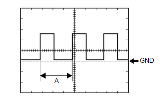
HINT:
When the system is functioning normally, one wheel revolution generates 4 pulses. As the vehicle speed increases, the width indicated by (A) in the illustration narrows.
- Waveform 2:
Item
Condition
Tester connection
G16-14 (FR) - G16-33 (FE)
Tool setting
2.5 V/DIV., 20 ms./DIV.
Condition
Engine switch on (IG), fuel level full → Fuel level low (fuel level warning light on)
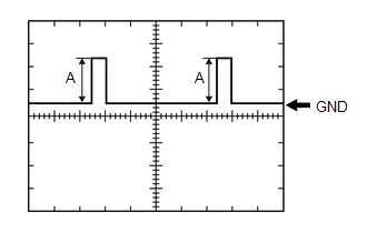
HINT:
- (A) will depending on the fuel level.
- Engine switch on (IG), fuel level full → Fuel level low (fuel level warning light on) (4.2 to 4.6 V → 0.3 to 1.7 V)
- Waveform 3:
Item
Condition
Tester connection
G16-15 (FV) - Body ground
Tool setting
2.5 V/DIV., 20 ms./DIV.
Condition
Engine switch on (IG)
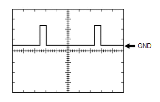
HINT:
Engine switch on (IG) (4.5 to 5.5 V)