Lost Communication with EMV Missing Message (B132187). Fuel Sender Circuit Open (B150013). Turn Signal Light Circuit Current Below Threshold (B150718)
Lost Communication with EMV Missing Message (B132187)
DESCRIPTION
The combination meter assembly and radio and display receiver assembly communicate via local bus communication. This allows audio and visual system information to be displayed on the multi-information display.
This DTC is stored when a communication error occurs between the radio and display receiver assembly and combination meter assembly.
DTC No. | Detection Item | DTC Detection Condition | Trouble Area | Memory | Note |
|---|---|---|---|---|---|
B132187 |
Lost Communication with EMV Missing Message |
Diagnosis Condition:
Malfunction Status:
Malfunction Time:
|
|
DTC stored |
- |
- *: w/ Headup Display System
WIRING DIAGRAM
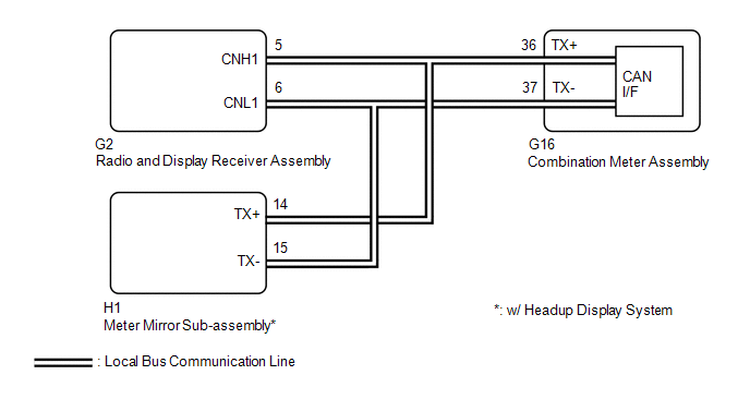
NOTICE:
When replacing the combination meter assembly, always replace it with a new one. If a combination meter assembly which was installed to another vehicle is used, the information stored in it will not match the information from the vehicle and a DTC may be stored.
PROCEDURE
CONFIRM MODEL
(a) Choose the model to be inspected.
Result | Proceed to |
|---|---|
w/o Headup Display System |
A |
w/ Headup Display System |
B |
| B |  |
GO TO STEP 4 |
|

CHECK FOR DTC (AUDIO AND VISUAL SYSTEM)
(a) Check if audio and visual system DTCs are output.
Body Electrical > Navigation System > Trouble CodesResult | Proceed to |
|---|---|
DTCs are not output |
A |
DTCs are output |
B |
| B | |
GO TO AUDIO AND VISUAL SYSTEM |
|
REPLACE COMBINATION METER ASSEMBLY
(a) Replace the combination meter assembly with a new one.
Click here 
(b) Turn the engine switch on (IG) and wait 30 seconds.
NOTICE:
A minimum of 30 seconds is required to send/receive the registration information between the combination meter assembly and radio and display receiver assembly.
(c) Operate the steering pad switch assembly and check that the audio tab illuminates.
(d) Check if meter / gauge system DTCs are output.
Body Electrical > Combination Meter > Trouble CodesResult | Proceed to |
|---|---|
The audio tab illuminates and DTC B132187 is not output |
A |
The audio tab does not illuminate and DTC B132187 is output |
B |
| A | |
END (COMBINATION METER ASSEMBLY WAS DEFECTIVE) |
| B | |
REPLACE RADIO AND DISPLAY RECEIVER ASSEMBLY |
CHECK FOR DTC (NAVIGATION SYSTEM)
(a) Check if navigation system DTCs are output.
Body Electrical > Navigation System > Trouble CodesResult | Proceed to |
|---|---|
DTCs are not output |
A |
DTCs are output |
B |
| B | |
GO TO NAVIGATION SYSTEM |
|
CHECK FOR DTC (HEADUP DISPLAY SYSTEM)
(a) Check if headup display system DTCs are output.
Body Electrical > Head Up Display > Trouble CodesResult | Proceed to |
|---|---|
DTC B132187 is not output |
A |
DTC B132187 is output |
B |
| A | |
REPLACE COMBINATION METER ASSEMBLY |
| B | |
REPLACE RADIO AND DISPLAY RECEIVER ASSEMBLY |
Fuel Sender Circuit Open (B150013)
DESCRIPTION
This DTC is stored when the combination meter assembly detects a fuel sender gauge assembly malfunction via a direct line.
DTC No. | Detection Item | DTC Detection Condition | Trouble Area | Memory | Note |
|---|---|---|---|---|---|
B150013 |
Fuel Sender Circuit Open |
Diagnosis Condition:
Malfunction Status:
|
|
DTC stored |
- |
WIRING DIAGRAM
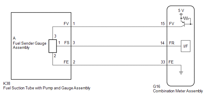
NOTICE:
When replacing the combination meter assembly, always replace it with a new one. If a combination meter assembly which was installed to another vehicle is used, the information stored in it will not match the information from the vehicle and a DTC may be stored.
PROCEDURE
READ VALUE USING TECHSTREAM
(a) Connect the Techstream to the DLC3.
(b) Turn the engine switch on (IG).
(c) Turn the Techstream on.
(d) Enter the following menus: Body Electrical / Combination Meter / Data List.
(e) Read the Data List according to the display on the Techstream.
Body Electrical > Combination Meter > Data ListTester Display | Measurement Item | Range | Normal Condition | Diagnostic Note |
|---|---|---|---|---|
Fuel Input |
Fuel input |
Min.: 0.00 L, Max.: 655.35 L or Unset |
for 60.6 liter (64.0 US qts, 53.3 Imp. qts) Fuel Tank:
for 55.0 liter (58.1 US qts, 48.4 Imp. qts) Fuel Tank:
|
- |
Fuel Input
Result | Proceed to |
|---|---|
Fuel level data can be displayed on the Techstream |
A |
Fuel level data cannot be displayed on the Techstream |
B |
| A |  |
REPLACE COMBINATION METER ASSEMBLY |
|

CHECK HARNESS AND CONNECTOR (FUEL SUCTION TUBE WITH PUMP AND GAUGE ASSEMBLY - COMBINATION METER ASSEMBLY)
(a) Disconnect the K38 fuel suction tube with pump and gauge assembly connector.
(b) Disconnect the G16 combination meter assembly connector.
(c) Measure the resistance according to the value(s) in the table below.
Standard Resistance:
Tester Connection | Condition | Specified Condition |
|---|---|---|
K38-1 (FV) - G16-15 (FV) |
Always |
Below 1 Ω |
K38-3 (FS) - G16-14 (FR) |
Always |
Below 1 Ω |
K38-2 (FE) - G16-33 (FE) |
Always |
Below 1 Ω |
K38-1 (FV) or G16-15 (FV) - Body ground |
Always |
10 kΩ or higher |
K38-3 (FS) or G16-14 (FR) - Body ground |
Always |
10 kΩ or higher |
| NG | |
REPAIR OR REPLACE HARNESS OR CONNECTOR |
|
INSPECT FUEL SENDER GAUGE ASSEMBLY
(a) Remove the fuel sender gauge assembly.
Click here 
(b) Inspect the fuel sender gauge assembly.
Click here
| NG | |
REPLACE FUEL SENDER GAUGE ASSEMBLY |
|
INSPECT FUEL SUCTION TUBE WITH PUMP AND GAUGE ASSEMBLY
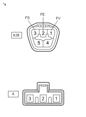
*a |
Component without harness connected (Fuel Suction Tube with Pump and Gauge Assembly) |
(a) Measure the resistance according to the value(s) in the table below.
Standard Resistance:
Tester Connection | Condition | Specified Condition |
|---|---|---|
K38-1 (FV) - A-3 |
Always |
Below 1 Ω |
K38-2 (FE) - A-2 |
Always |
Below 1 Ω |
K38-3 (FS) - A-1 |
Always |
Below 1 Ω |
K38-1 (FV) - K38-3 (FS) or A-3 - A-1 |
Always |
10 kΩ or higher |
K38-1 (FV) - K38-2 (FE) or A-3 - A-2 |
Always |
10 kΩ or higher |
K38-2 (FE) - K38-3 (FS) or A-2 - A-1 |
Always |
10 kΩ or higher |
| OK | |
REPLACE COMBINATION METER ASSEMBLY |
| NG | |
REPLACE FUEL SUCTION TUBE WITH PUMP AND GAUGE ASSEMBLY |
Turn Signal Light Circuit Current Below Threshold (B150718)
DESCRIPTION
This DTC is stored when the combination meter assembly detects an open in a front turn signal light circuit or rear turn signal light circuit.
HINT:
- If there is an open in a front turn signal light circuit or rear turn signal light circuit, the turn signal lights on the side with the open circuit will blink faster than usual.
- If there is an open in a side turn signal light circuit, DTC B150718 will not be stored.
DTC No. | Detection Item | DTC Detection Condition | Trouble Area | Memory | Note |
|---|---|---|---|---|---|
B150718 |
Turn Signal Light Circuit Current Below Threshold |
Diagnosis Condition:
Malfunction Status:
|
|
DTC stored |
- |
- *: w/ Cornering Light
WIRING DIAGRAM
LH SIDE
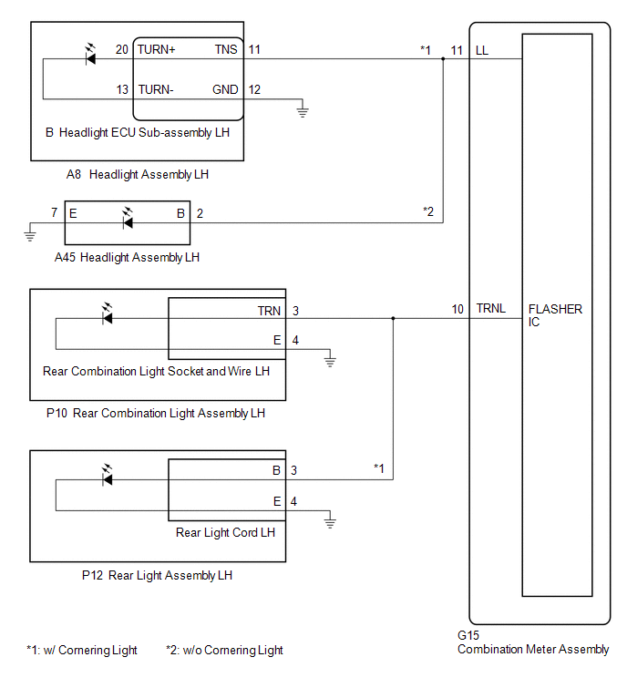
RH SIDE
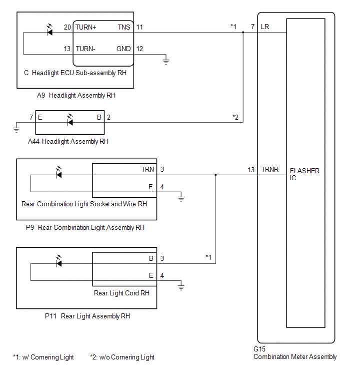
NOTICE:
When replacing the combination meter assembly, always replace it with a new one. If a combination meter assembly which was installed to another vehicle is used, the information stored in it will not match the information from the vehicle and a DTC may be stored.
PROCEDURE
INSPECT LIGHTS
(a) Inspect the illumination of each turn signal light.
Result | Proceed to |
|---|---|
Front turn signal light LH does not blink |
A |
Rear turn signal light LH does not blink |
B |
Front turn signal light RH does not blink |
C |
Rear turn signal light RH does not blink |
D |
| B |  |
GO TO STEP 8 |
| C | |
GO TO STEP 18 |
| D | |
GO TO STEP 24 |
|

CONFIRM MODEL
(a) Choose the model to be inspected.
Result | Proceed to |
|---|---|
w/ Cornering Light |
A |
w/o Cornering Light |
B |
| B | |
GO TO STEP 6 |
|
CHECK HARNESS AND CONNECTOR (HEADLIGHT ASSEMBLY LH - COMBINATION METER ASSEMBLY AND BODY GROUND)
(a) Disconnect the A8 headlight assembly LH connector.
(b) Disconnect the G15 combination meter assembly connector.
(c) Measure the resistance according to the value(s) in the table below.
Standard Resistance:
Tester Connection | Condition | Specified Condition |
|---|---|---|
A8-11 (TNS) - G15-11 (LL) |
Always |
Below 1 Ω |
A8-12 (GND) - Body ground |
Always |
Below 1 Ω |
| NG | |
REPAIR OR REPLACE HARNESS OR CONNECTOR |
|
INSPECT HEADLIGHT ECU SUB-ASSEMBLY LH
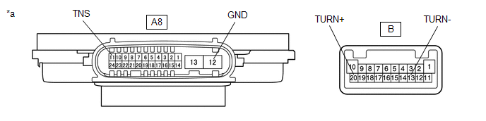
*a |
Component without harness connected (Headlight ECU Sub-assembly LH) |
- |
- |
(a) Remove the headlight ECU sub-assembly LH.
Click here 
(b) Measure the resistance according to the value(s) in the table below.
Standard Resistance:
Tester Connection | Condition | Specified Condition |
|---|---|---|
B-20 (TURN+) - A8-11 (TNS) |
Always |
Below 1 Ω |
B-13 (TURN-) - A8-12 (GND) |
Always |
Below 1 Ω |
| NG | |
REPLACE HEADLIGHT ECU SUB-ASSEMBLY LH |
|
CHECK HEADLIGHT ASSEMBLY LH
(a) Connect the G15 combination meter assembly connector.
(b) Remove each headlight ECU sub-assembly, interchange the headlight assembly LH with RH and connect the connectors.
Click here
(c) Check that the front turn signal light operates normally.
OK:
Front turn signal light blinks.
| OK | |
REPLACE HEADLIGHT ASSEMBLY LH |
| NG | |
REPLACE COMBINATION METER ASSEMBLY |
CHECK HARNESS AND CONNECTOR (HEADLIGHT ASSEMBLY LH - COMBINATION METER ASSEMBLY AND BODY GROUND)
(a) Disconnect the A45 headlight assembly LH connector.
(b) Disconnect the G15 combination meter assembly connector.
(c) Measure the resistance according to the value(s) in the table below.
Standard Resistance:
Tester Connection | Condition | Specified Condition |
|---|---|---|
A45-2 (B) - G15-11 (LL) |
Always |
Below 1 Ω |
A45-7 (E) - Body ground |
Always |
Below 1 Ω |
| NG | |
REPAIR OR REPLACE HARNESS OR CONNECTOR |
|
CHECK HEADLIGHT ASSEMBLY LH
(a) Connect the G15 combination meter assembly connector.
(b) Interchange the headlight assembly LH with RH and connect the connectors.
Click here
(c) Check that the front turn signal light operates normally.
OK:
Front turn signal light blinks.
| OK | |
REPLACE HEADLIGHT ASSEMBLY LH |
| NG | |
REPLACE COMBINATION METER ASSEMBLY |
CONFIRM MODEL
(a) Choose the model to be inspected.
Result | Proceed to |
|---|---|
w/ Cornering Light |
A |
w/o Cornering Light |
B |
| B | |
GO TO STEP 15 |
|
CHECK HARNESS AND CONNECTOR (REAR COMBINATION LIGHT ASSEMBLY LH - COMBINATION METER ASSEMBLY AND BODY GROUND)
(a) Disconnect the P10 rear combination light assembly LH connector.
(b) Disconnect the G15 combination meter assembly connector.
(c) Measure the resistance according to the value(s) in the table below.
Standard Resistance:
Tester Connection | Condition | Specified Condition |
|---|---|---|
P10-3 (TRN) - G15-10 (TRNL) |
Always |
Below 1 Ω |
P10-4 (E) - Body ground |
Always |
Below 1 Ω |
| NG | |
REPAIR OR REPLACE HARNESS OR CONNECTOR |
|
CHECK REAR COMBINATION LIGHT SOCKET AND WIRE LH
(a) Connect the G15 combination meter assembly connector.
(b) Interchange the rear combination light socket and wire LH with RH and connect the connectors.
Click here
(c) Check that the rear turn signal light operates normally.
OK:
Rear turn signal light blinks.
| OK | |
REPLACE REAR COMBINATION LIGHT SOCKET AND WIRE LH |
|
INSPECT REAR COMBINATION LIGHT ASSEMBLY LH
(a) Remove the rear combination light assembly LH.
Click here
(b) Inspect the rear combination light assembly LH.
Click here
| NG | |
REPLACE REAR COMBINATION LIGHT ASSEMBLY LH |
|
CHECK HARNESS AND CONNECTOR (REAR LIGHT ASSEMBLY LH - COMBINATION METER ASSEMBLY AND BODY GROUND)
(a) Disconnect the P12 rear light assembly LH connector.
(b) Disconnect the G15 combination meter assembly connector.
(c) Measure the resistance according to the value(s) in the table below.
Standard Resistance:
Tester Connection | Condition | Specified Condition |
|---|---|---|
P12-3 (B) - G15-10 (TRNL) |
Always |
Below 1 Ω |
P12-4 (E) - Body ground |
Always |
Below 1 Ω |
| NG | |
REPAIR OR REPLACE HARNESS OR CONNECTOR |
|
CHECK REAR LIGHT CORD LH
(a) Connect the G15 combination meter assembly connector.
(b) Interchange the rear light cord LH with RH and connect the connectors.
Click here
(c) Check that the rear turn signal light operates normally.
OK:
Rear turn signal light blinks.
| OK | |
REPLACE REAR LIGHT CORD LH |
|
INSPECT REAR LIGHT ASSEMBLY LH
(a) Remove the rear light assembly LH.
Click here
(b) Inspect the rear light assembly LH.
Click here
| OK | |
REPLACE COMBINATION METER ASSEMBLY |
| NG | |
REPLACE REAR LIGHT ASSEMBLY LH |
CHECK HARNESS AND CONNECTOR (REAR COMBINATION LIGHT ASSEMBLY LH - COMBINATION METER ASSEMBLY AND BODY GROUND)
(a) Disconnect the P10 rear combination light assembly LH connector.
(b) Disconnect the G15 combination meter assembly connector.
(c) Measure the resistance according to the value(s) in the table below.
Standard Resistance:
Tester Connection | Condition | Specified Condition |
|---|---|---|
P10-3 (TRN) - G15-10 (TRNL) |
Always |
Below 1 Ω |
P10-4 (E) - Body ground |
Always |
Below 1 Ω |
| NG | |
REPAIR OR REPLACE HARNESS OR CONNECTOR |
|
CHECK REAR COMBINATION LIGHT SOCKET AND WIRE LH
(a) Connect the G15 combination meter assembly connector.
(b) Interchange the rear combination light socket and wire LH with RH and connect the connectors.
Click here
(c) Check that the rear turn signal light operates normally.
OK:
Rear turn signal light blinks.
| OK | |
REPLACE REAR COMBINATION LIGHT SOCKET AND WIRE LH |
|
INSPECT REAR COMBINATION LIGHT ASSEMBLY LH
(a) Remove the rear combination light assembly LH.
Click here
(b) Inspect the rear combination light assembly LH.
Click here
| OK | |
REPLACE COMBINATION METER ASSEMBLY |
| NG | |
REPLACE REAR COMBINATION LIGHT ASSEMBLY LH |
CONFIRM MODEL
(a) Choose the model to be inspected.
Result | Proceed to |
|---|---|
w/ Cornering Light |
A |
w/o Cornering Light |
B |
| B | |
GO TO STEP 22 |
|
CHECK HARNESS AND CONNECTOR (HEADLIGHT ASSEMBLY RH - COMBINATION METER ASSEMBLY AND BODY GROUND)
(a) Disconnect the A9 headlight assembly RH connector.
(b) Disconnect the G15 combination meter assembly connector.
(c) Measure the resistance according to the value(s) in the table below.
Standard Resistance:
Tester Connection | Condition | Specified Condition |
|---|---|---|
A9-11 (TNS) - G15-7 (LR) |
Always |
Below 1 Ω |
A9-12 (GND) - Body ground |
Always |
Below 1 Ω |
| NG | |
REPAIR OR REPLACE HARNESS OR CONNECTOR |
|
INSPECT HEADLIGHT ECU SUB-ASSEMBLY RH
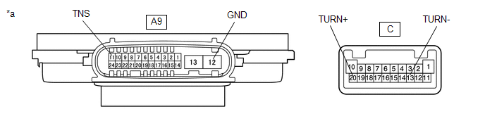
*a |
Component without harness connected (Headlight ECU Sub-assembly RH) |
- |
- |
(a) Remove the headlight ECU sub-assembly RH.
Click here
(b) Measure the resistance according to the value(s) in the table below.
Standard Resistance:
Tester Connection | Condition | Specified Condition |
|---|---|---|
C-20 (TURN+) - A9-11 (TNS) |
Always |
Below 1 Ω |
C-13 (TURN-) - A9-12 (GND) |
Always |
Below 1 Ω |
| NG | |
REPLACE HEADLIGHT ECU SUB-ASSEMBLY RH |
|
CHECK HEADLIGHT ASSEMBLY RH
(a) Connect the G15 combination meter assembly connector.
(b) Remove each headlight ECU sub-assembly, interchange the headlight assembly RH with LH and connect the connectors.
Click here
(c) Check that the front turn signal light operates normally.
OK:
Front turn signal light blinks.
| OK | |
REPLACE HEADLIGHT ASSEMBLY RH |
| NG | |
REPLACE COMBINATION METER ASSEMBLY |
CHECK HARNESS AND CONNECTOR (HEADLIGHT ASSEMBLY RH - COMBINATION METER ASSEMBLY AND BODY GROUND)
(a) Disconnect the A44 headlight assembly RH connector.
(b) Disconnect the G15 combination meter assembly connector.
(c) Measure the resistance according to the value(s) in the table below.
Standard Resistance:
Tester Connection | Condition | Specified Condition |
|---|---|---|
A44-2 (B) - G15-7 (LR) |
Always |
Below 1 Ω |
A44-7 (E) - Body ground |
Always |
Below 1 Ω |
| NG | |
REPAIR OR REPLACE HARNESS OR CONNECTOR |
|
CHECK HEADLIGHT ASSEMBLY RH
(a) Connect the G15 combination meter assembly connector.
(b) Interchange the headlight assembly RH with LH and connect the connectors.
Click here
(c) Check that the front turn signal light operates normally.
OK:
Front turn signal light blinks.
| OK | |
REPLACE HEADLIGHT ASSEMBLY RH |
| NG | |
REPLACE COMBINATION METER ASSEMBLY |
CONFIRM MODEL
(a) Choose the model to be inspected.
Result | Proceed to |
|---|---|
w/ Cornering Light |
A |
w/o Cornering Light |
B |
| B | |
GO TO STEP 31 |
|
CHECK HARNESS AND CONNECTOR (REAR COMBINATION LIGHT ASSEMBLY RH - COMBINATION METER ASSEMBLY AND BODY GROUND)
(a) Disconnect the P9 rear combination light assembly RH connector.
(b) Disconnect the G15 combination meter assembly connector.
(c) Measure the resistance according to the value(s) in the table below.
Standard Resistance:
Tester Connection | Condition | Specified Condition |
|---|---|---|
P9-3 (TRN) - G15-13 (TRNR) |
Always |
Below 1 Ω |
P9-4 (E) - Body ground |
Always |
Below 1 Ω |
| NG | |
REPAIR OR REPLACE HARNESS OR CONNECTOR |
|
CHECK REAR COMBINATION LIGHT SOCKET AND WIRE RH
(a) Connect the G15 combination meter assembly connector.
(b) Interchange the rear combination light socket and wire RH with LH and connect the connectors.
Click here
(c) Check that the rear turn signal light operates normally.
OK:
Rear turn signal light blinks.
| OK | |
REPLACE REAR COMBINATION LIGHT SOCKET AND WIRE RH |
|
INSPECT REAR COMBINATION LIGHT ASSEMBLY RH
(a) Remove the rear combination light assembly RH.
Click here
(b) Inspect the rear combination light assembly RH.
Click here
| NG | |
REPLACE REAR COMBINATION LIGHT ASSEMBLY RH |
|
CHECK HARNESS AND CONNECTOR (REAR LIGHT ASSEMBLY RH - COMBINATION METER ASSEMBLY AND BODY GROUND)
(a) Disconnect the P11 rear light assembly RH connector.
(b) Disconnect the G15 combination meter assembly connector.
(c) Measure the resistance according to the value(s) in the table below.
Standard Resistance:
Tester Connection | Condition | Specified Condition |
|---|---|---|
P11-3 (B) - G15-13 (TRNR) |
Always |
Below 1 Ω |
P11-4 (E) - Body ground |
Always |
Below 1 Ω |
| NG | |
REPAIR OR REPLACE HARNESS OR CONNECTOR |
|
CHECK REAR LIGHT CORD RH
(a) Connect the G15 combination meter assembly connector.
(b) Interchange the rear light cord RH with LH and connect the connectors.
Click here
(c) Check that the rear turn signal light operates normally.
OK:
Rear turn signal light blinks.
| OK | |
REPLACE REAR LIGHT CORD RH |
|
INSPECT REAR LIGHT ASSEMBLY RH
(a) Remove the rear light assembly RH.
Click here
(b) Inspect the rear light assembly RH.
Click here
| OK | |
REPLACE COMBINATION METER ASSEMBLY |
| NG | |
REPLACE REAR LIGHT ASSEMBLY RH |
CHECK HARNESS AND CONNECTOR (REAR COMBINATION LIGHT ASSEMBLY RH - COMBINATION METER ASSEMBLY AND BODY GROUND)
(a) Disconnect the P9 rear combination light assembly RH connector.
(b) Disconnect the G15 combination meter assembly connector.
(c) Measure the resistance according to the value(s) in the table below.
Standard Resistance:
Tester Connection | Condition | Specified Condition |
|---|---|---|
P9-3 (TRN) - G15-13 (TRNR) |
Always |
Below 1 Ω |
P9-4 (E) - Body ground |
Always |
Below 1 Ω |
| NG | |
REPAIR OR REPLACE HARNESS OR CONNECTOR |
|
CHECK REAR COMBINATION LIGHT SOCKET AND WIRE RH
(a) Connect the G15 combination meter assembly connector.
(b) Interchange the rear combination light socket and wire RH with LH and connect the connectors.
Click here
(c) Check that the rear turn signal light operates normally.
OK:
Rear turn signal light blinks.
| OK | |
REPLACE REAR COMBINATION LIGHT SOCKET AND WIRE RH |
|
INSPECT REAR COMBINATION LIGHT ASSEMBLY RH
(a) Remove the rear combination light assembly RH.
Click here
(b) Inspect the rear combination light assembly RH.
Click here
| OK | |
REPLACE COMBINATION METER ASSEMBLY |
| NG | |
REPLACE REAR COMBINATION LIGHT ASSEMBLY RH |