Fuel Pressure Sensor(for High Pressure)
Components
COMPONENTS
ILLUSTRATION
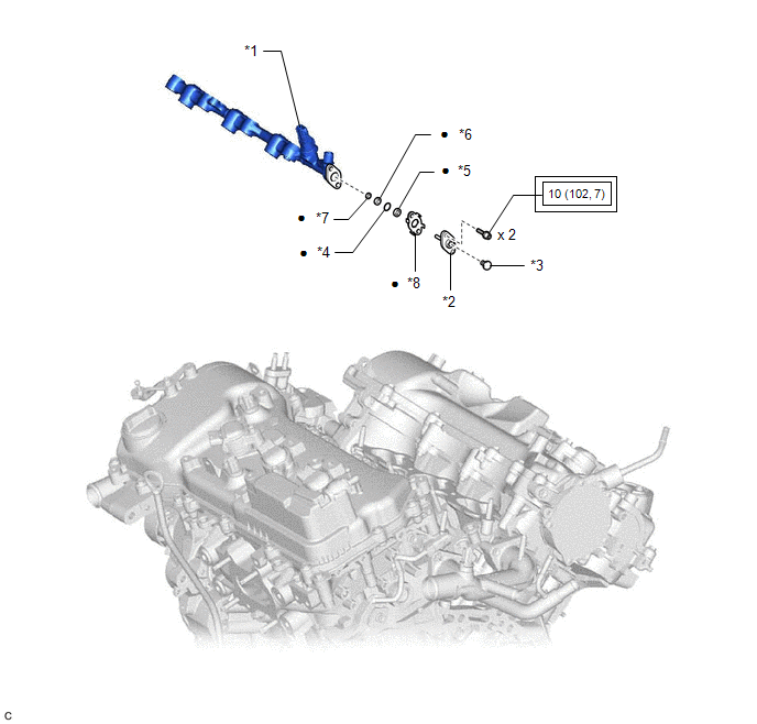
*1 |
FUEL PRESSURE SENSOR (FUEL DELIVERY PIPE WITH SENSOR ASSEMBLY LH) |
*2 |
FUEL PIPE PLUG SUB-ASSEMBLY |
*3 |
DUST CAP SUB-ASSEMBLY |
*4 |
O-RING |
*5 |
NO. 1 FUEL INJECTOR BACK-UP RING |
*6 |
NO. 2 FUEL INJECTOR BACK-UP RING |
*7 |
NO. 3 FUEL INJECTOR BACK-UP RING |
*8 |
GASKET |
 |
Tightening torque for "Major areas involving basic vehicle performance such as moving/turning/stopping": N*m (kgf*cm, ft.*lbf) |
● |
Non-reusable part |
Inspection
INSPECTION
PROCEDURE
1. INSPECT FUEL PRESSURE SENSOR (FUEL DELIVERY PIPE WITH SENSOR ASSEMBLY LH)
NOTICE:
- Do not remove the fuel pressure sensor from the fuel delivery pipe with sensor assembly LH.
- If the fuel pressure sensor is removed, replace the fuel pressure sensor (fuel delivery pipe with sensor assembly LH) with a new one.
(a) Check the fuel pressure sensor output voltage.
(1) Apply 5 V between terminals 1 (VC) and 2 (E2). NOTICE:
HINT: If a stable power supply is not available, connect 4 nickel-metal hydride batteries (1.2 V each) or equivalent in series. |
|
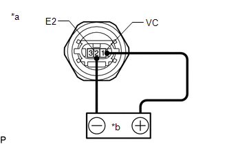
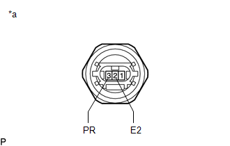
(2) Measure the voltage according to the value(s) in the table below. Standard Voltage:
*: The output voltage changes depending on the voltage applied to the terminals. If the result is not as specified, replace the fuel pressure sensor (fuel delivery pipe with sensor assembly LH). |
|
Installation
INSTALLATION
PROCEDURE
1. INSTALL FUEL PIPE PLUG SUB-ASSEMBLY
(a) Install a new O-ring, No. 1 fuel injector back-up ring, No. 2 fuel injector back-up ring and No. 3 fuel injector back-up ring to the fuel pipe plug sub-assembly as shown in the illustration.
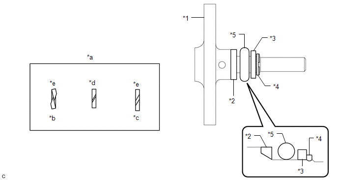
*1 |
Fuel Pipe Plug Sub-assembly |
*2 |
No. 1 Fuel Injector Back-up Ring |
*3 |
No. 2 Fuel Injector Back-up Ring |
*4 |
No. 3 Fuel Injector Back-up Ring |
*5 |
O-ring |
- |
- |
*a |
Opening |
*b |
Overlapped |
*c |
Stretched |
*d |
Correct |
*e |
Incorrect |
- |
- |
NOTICE:
- Check that there is no foreign matter or damage on the O-ring groove of the fuel pipe plug sub-assembly.
- Check that the No. 1 fuel injector back-up ring and No. 3 fuel injector back-up ring are installed in the correct orientation.
- Make sure that the No. 1 fuel injector back-up ring, No. 2 fuel injector back-up ring, No. 3 fuel injector back-up ring and O-ring are installed in the correct order.
- Check that the opening of the No. 1 fuel injector back-up ring is not overlapped or stretched as shown in the illustration.
- After installing the O-ring, check that it is not contaminated with foreign matter and is not damaged.
(b) Install the dust cap sub-assembly to the fuel pipe plug sub-assembly.
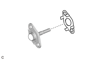
(c) Install a new gasket to the fuel pipe plug sub-assembly as shown in the illustration. |
 |
(d) Secure the fuel delivery pipe with sensor assembly LH in a vise between aluminum plates.
NOTICE:
Do not overtighten the vise.
(e) Using a 5 mm hexagon socket wrench, install the fuel pipe plug sub-assembly to the fuel delivery pipe with sensor assembly LH with the 2 bolts.
Torque:
10 N·m {102 kgf·cm, 7 ft·lbf}
(f) Remove the fuel delivery pipe with sensor assembly LH from the vise.
2. INSTALL FUEL PRESSURE SENSOR (FUEL DELIVERY PIPE WITH SENSOR ASSEMBLY LH)
HINT:
Perform "Inspection After Repair" after replacing the fuel pressure sensor (fuel delivery pipe with sensor assembly LH).
Click here 
Click here
NOTICE:
- Do not remove the fuel pressure sensor from the fuel delivery pipe with sensor assembly LH.
- If the fuel pressure sensor is removed, replace the fuel pressure sensor (fuel delivery pipe with sensor assembly LH) with a new one.
3. PERFORM INITIALIZATION
(a) Perform "Inspection After Repair" after replacing the fuel pressure sensor (fuel delivery pipe with sensor assembly LH).
Click here
Removal
REMOVAL
The necessary procedures (adjustment, calibration, initialization or registration) that must be performed after parts are removed and installed, or replaced during fuel pressure sensor (fuel delivery pipe with sensor assembly LH) removal/installation are shown below.
Necessary Procedures After Parts Removed/Installed/ReplacedReplaced Part or Performed Procedure | Necessary Procedure | Effect/Inoperative Function when Necessary Procedure not Performed | Link |
|---|---|---|---|
| *: When performing learning using the Techstream. Click here |
|||
Battery terminal is disconnected/reconnected |
Perform steering sensor zero point calibration |
Lane Departure Alert System (w/ Steering Control) |
 |
Pre-collision System |
|||
Intelligent Clearance Sonar System* |
|||
Lighting System (for Gasoline Model with Cornering Light) |
|||
Memorize steering angle neutral point |
Parking Assist Monitor System |
|
|
Panoramic View Monitor System |
|
||
|
Inspection after repair |
|
|
CAUTION:
- Never perform work on fuel system components near any possible ignition sources.
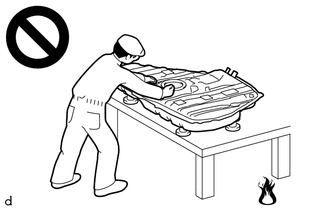
- Vaporized fuel could ignite, resulting in a serious accident.
- Do not perform work on fuel system components without first disconnecting the cable from the negative (-) battery terminal.
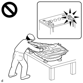
- Sparks could cause vaporized fuel to ignite, resulting in a serious accident.
PROCEDURE
1. REMOVE FUEL PRESSURE SENSOR (FUEL DELIVERY PIPE WITH SENSOR ASSEMBLY LH)
Click here
NOTICE:
- Do not remove the fuel pressure sensor from the fuel delivery pipe with sensor assembly LH.
- If the fuel pressure sensor is removed, replace the fuel pressure sensor (fuel delivery pipe with sensor assembly LH) with a new one.
2. REMOVE FUEL PIPE PLUG SUB-ASSEMBLY
(a) Secure the fuel delivery pipe with sensor assembly LH in a vise between aluminum plates. NOTICE: Do not overtighten the vise. |
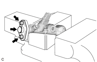 |
(b) Using a 5 mm hexagon socket wrench, remove the 2 bolts, gasket and fuel pipe plug sub-assembly from the fuel delivery pipe with sensor assembly LH.
(c) Remove the dust cap sub-assembly from the fuel pipe plug sub-assembly.
(d) Remove the O-ring, No. 1 fuel injector back-up ring, No. 2 fuel injector back-up ring and No. 3 fuel injector back-up ring from the fuel pipe plug sub-assembly.
(e) Remove the fuel delivery pipe with sensor assembly LH from the vise.