Fuel Pump Ecu
Components
COMPONENTS
ILLUSTRATION
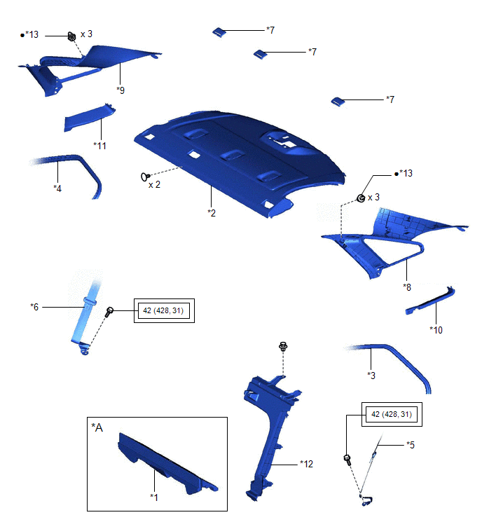
*A |
w/o Seat Heater System |
- |
- |
*1 |
LUGGAGE COMPARTMENT INNER TRIM PAD |
*2 |
PACKAGE TRAY TRIM PANEL ASSEMBLY |
*3 |
REAR DOOR OPENING TRIM WEATHERSTRIP LH |
*4 |
REAR DOOR OPENING TRIM WEATHERSTRIP RH |
*5 |
REAR SEAT 3 POINT TYPE BELT ASSEMBLY LH |
*6 |
REAR SEAT 3 POINT TYPE BELT ASSEMBLY RH |
*7 |
REAR SEAT SHOULDER BELT COVER |
*8 |
ROOF SIDE INNER GARNISH LH |
*9 |
ROOF SIDE INNER GARNISH RH |
*10 |
ROOF SIDE RAIL GARNISH ASSEMBLY LH |
*11 |
ROOF SIDE RAIL GARNISH ASSEMBLY RH |
*12 |
ROOM PARTITION BOARD LH |
*13 |
CLIP |
- |
- |
 |
Tightening torque for "Major areas involving basic vehicle performance such as moving/turning/stopping": N*m (kgf*cm, ft.*lbf) |
● |
Non-reusable part |
ILLUSTRATION
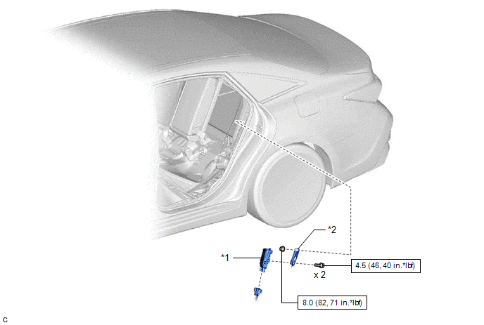
*1 |
FUEL PUMP CONTROL ECU |
*2 |
FUEL PUMP CONTROL ECU BRACKET |
 |
N*m (kgf*cm, ft.*lbf): Specified torque |
- |
- |
Installation
INSTALLATION
PROCEDURE
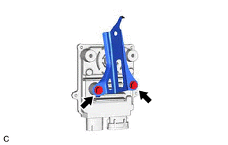
1. INSTALL FUEL PUMP CONTROL ECU BRACKET
(a) Install the fuel pump control ECU bracket to the fuel pump control ECU with the 2 bolts.
Torque:
4,5 N·m {46 kgf·cm, 40 in·lbf}
2. INSTALL FUEL PUMP CONTROL ECU
(a) Install the fuel pump control ECU to the vehicle body with the nut.
Torque:
8 N·m {82 kgf·cm, 71 in·lbf}
(b) Connect the 2 fuel pump control ECU connectors.
3. INSTALL ROOM PARTITION BOARD LH
Click here 
4. INSTALL PACKAGE TRAY TRIM PANEL ASSEMBLY
Click here
5. INSTALL REAR SEAT SHOULDER BELT COVER
Click here
6. INSTALL ROOF SIDE INNER GARNISH LH
Click here
7. INSTALL ROOF SIDE INNER GARNISH RH
HINT:
Use the same procedure as for the LH side.
8. INSTALL ROOF SIDE RAIL GARNISH ASSEMBLY LH
Click here
9. INSTALL ROOF SIDE RAIL GARNISH ASSEMBLY RH
HINT:
Use the same procedure as for the LH side.
10. CONNECT REAR DOOR OPENING TRIM WEATHERSTRIP LH
Click here
11. CONNECT REAR DOOR OPENING TRIM WEATHERSTRIP RH
Click here
12. CONNECT REAR SEAT 3 POINT TYPE BELT ASSEMBLY LH
Click here
13. CONNECT REAR SEAT 3 POINT TYPE BELT ASSEMBLY RH
HINT:
Use the same procedure as for the LH side.
14. INSTALL CENTER STOP LIGHT SET
Click here
15. INSTALL LUGGAGE COMPARTMENT INNER TRIM PAD (w/o Seat Heater System)
Click here
16. INSTALL REAR SEAT ASSEMBLY
Click here
Removal
REMOVAL
The necessary procedures (adjustment, calibration, initialization or registration) that must be performed after parts are removed and installed, or replaced during fuel pump control ECU removal/installation are shown below.
Necessary Procedures After Parts Removed/Installed/ReplacedReplaced Part or Performed Procedure | Necessary Procedure | Effect/Inoperative Function when Necessary Procedure not Performed | Link |
|---|---|---|---|
| *: When performing learning using the Techstream. Click here |
|||
Battery terminal is disconnected/reconnected |
Perform steering sensor zero point calibration |
Lane Departure Alert System (w/ Steering Control) |
 |
Pre-collision System |
|||
Intelligent Clearance Sonar System* |
|||
Lighting System (for Gasoline Model with Cornering Light) |
|||
Memorize steering angle neutral point |
Parking Assist Monitor System |
|
|
Panoramic View Monitor System |
|
||
PROCEDURE
1. REMOVE REAR SEAT ASSEMBLY
Click here
2. REMOVE CENTER STOP LIGHT SET
Click here
3. REMOVE LUGGAGE COMPARTMENT INNER TRIM PAD (w/o Seat Heater System)
Click here
4. DISCONNECT REAR SEAT 3 POINT TYPE BELT ASSEMBLY LH
Click here
5. DISCONNECT REAR SEAT 3 POINT TYPE BELT ASSEMBLY RH
HINT:
Use the same procedure as for the LH side.
6. DISCONNECT REAR DOOR OPENING TRIM WEATHERSTRIP LH
Click here
7. DISCONNECT REAR DOOR OPENING TRIM WEATHERSTRIP RH
HINT:
Use the same procedure as for the LH side.
8. REMOVE ROOF SIDE RAIL GARNISH ASSEMBLY LH
Click here
9. REMOVE ROOF SIDE RAIL GARNISH ASSEMBLY RH
HINT:
Use the same procedure as for the LH side.
10. REMOVE ROOF SIDE INNER GARNISH LH
Click here
11. REMOVE ROOF SIDE INNER GARNISH RH
HINT:
Use the same procedure as for the LH side.
12. REMOVE REAR SEAT SHOULDER BELT COVER
Click here
13. REMOVE PACKAGE TRAY TRIM PANEL ASSEMBLY
Click here
14. REMOVE ROOM PARTITION BOARD LH
Click here
15. REMOVE FUEL PUMP CONTROL ECU
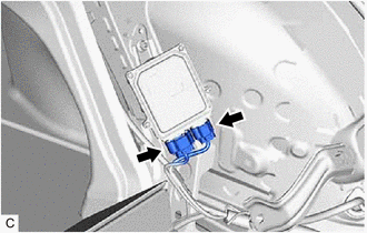
(a) Disconnect the 2 fuel pump control ECU connectors. |
 |
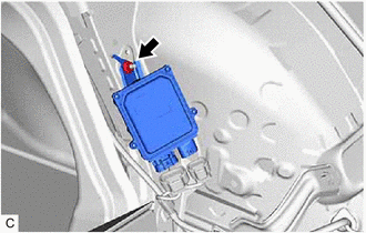
(b) Remove the nut and fuel pump control ECU from the vehicle body. NOTICE: Do not reuse the fuel pump control ECU if it has been dropped or subjected to a severe impact. |
 |
16. REMOVE FUEL PUMP CONTROL ECU BRACKET
(a) Remove the 2 bolts and fuel pump control ECU bracket from the fuel pump control ECU. |
 |