Camshaft Position Signal Output "A" General Electrical Failure (P261401). Engine Coolant Bypass Valve Circuit Short to Ground (P268111,P268115). Poor Engine Power (P319000,P319100)
Camshaft Position Signal Output "A" General Electrical Failure (P261401)
DESCRIPTION
Refer to DTC P001001.
Click here 
DTC No. | Detection Item | DTC Detection Condition | Trouble Area | MIL | Memory | Note |
|---|---|---|---|---|---|---|
P261401 |
Camshaft Position Signal Output "A" General Electrical Failure |
Malfunction in rotation sensor of cam timing control motor with EDU assembly is detected for 3 seconds (1 trip detection logic). |
|
Comes on |
DTC stored |
SAE Code: P2614 |
Vehicle Condition | Fail-Safe |
|---|---|
|
The cam timing control motor with EDU assembly is operated to the most retarded position. |
MONITOR DESCRIPTION
This DTC is output when a malfunction in the cam timing control motor rotation sensor is detected. The cam timing control motor with EDU assembly is equipped with a self diagnostic function, which is used to output diagnosis signals (VTM) to the ECM. If the ECM receives a duty signal of 40%, this DTC is output immediately (1 trip detection logic).
MONITOR STRATEGY
Related DTC |
P2614: Camshaft position signal range check |
Required sensor/Components (Main) |
Cam timing control motor with EDU assembly |
Required sensor/Components (Related) |
- |
Frequency of Operation |
Continuous |
Duration |
3 seconds |
MIL Operation |
Immediate |
Sequence of Operation |
None |
TYPICAL ENABLING CONDITIONS
Monitor runs whenever the following DTCs are not stored |
None |
All of the following conditions are met |
- |
Auxiliary battery voltage |
11 V or higher |
Power switch |
On (IG) |
Engine speed |
100 rpm or higher |
TYPICAL MALFUNCTION THRESHOLDS
"Camshaft position signal error" from motor drive VVT system control module |
Received |
CONFIRMATION DRIVING PATTERN
HINT:
- After repair has been completed, clear the DTC and then check that the vehicle has returned to normal by performing the following All Readiness check procedure.
Click here
- When clearing the permanent DTCs, refer to the "CLEAR PERMANENT DTC" procedure.
Click here
- Connect the Techstream to the DLC3.
- Turn the power switch on (IG).
- Turn the Techstream on.
- Clear the DTCs (even if no DTCs are stored, perform the clear DTC procedure).
- Turn the power switch off and wait for at least 30 seconds.
- Turn the power switch on (IG).
- Turn the Techstream on.
- Put the engine in Inspection Mode (Maintenance Mode).
Click here
- Start the engine [A].
- Idle the engine for 10 seconds or more [B].
- Enter the following menus: Powertrain / Engine / Trouble Codes [C].
- Read the pending DTCs.
HINT:
- If a pending DTC is output, the system is malfunctioning.
- If a pending DTC is not output, perform the following procedure.
- Enter the following menus: Powertrain / Engine / Utility / All Readiness.
- Input the DTC: P261401.
- Check the DTC judgment result.
Techstream Display
Description
NORMAL
- DTC judgment completed
- System normal
ABNORMAL
- DTC judgment completed
- System abnormal
INCOMPLETE
- DTC judgment not completed
- Perform driving pattern after confirming DTC enabling conditions
HINT:
- If the judgment result is NORMAL, the system is normal.
- If the judgment result is ABNORMAL, the system has a malfunction.
- If the judgment result is INCOMPLETE, perform steps [A] through [C] again.
- [A] to [C]: Normal judgment procedure.
The normal judgment procedure is used to complete DTC judgment and also used when clearing permanent DTCs.
- When clearing the permanent DTCs, do not disconnect the cable from the auxiliary battery terminal or attempt to clear the DTCs during this procedure, as doing so will clear the universal trip and normal judgment histories.
NOTICE:
- Vehicle Control History may be stored in the hybrid vehicle control ECU assembly if the engine is malfunctioning. Certain vehicle condition information is recorded when Vehicle Control History is stored. Reading the vehicle conditions recorded in both the Freeze Frame Data and Vehicle Control History can be useful for troubleshooting.
Click here
(Select Powertrain in Health Check and then check the time stamp data.)
Click here
- If any "Engine Malfunction" Vehicle Control History item has been stored in the hybrid vehicle control ECU assembly, make sure to clear it. However, as all Vehicle Control History items are cleared simultaneously, if any Vehicle Control History items other than "Engine Malfunction" are stored, make sure to perform any troubleshooting for them before clearing Vehicle Control History.
Click here
HINT:
Read Freeze Frame Data using the Techstream. The ECM records vehicle and driving condition information as Freeze Frame Data the moment a DTC is stored. When troubleshooting, Freeze Frame Data can help determine if the vehicle was moving or stationary, if the engine was warmed up or not, if the air fuel ratio was lean or rich, and other data from the time the malfunction occurred.
PROCEDURE
REPLACE CAM TIMING CONTROL MOTOR WITH EDU ASSEMBLY
(a) Replace the cam timing control motor with EDU assembly.
Click here
HINT:
Perform "Inspection After Repair" after replacing the cam timing control motor with EDU assembly.
Click here
|

CLEAR DTC
(a) Connect the Techstream to the DLC3.
(b) Turn the power switch on (IG).
(c) Turn the Techstream on.
(d) Clear the DTCs.
Powertrain > Engine > Clear DTCs(e) Turn the power switch off and wait for at least 30 seconds.
|
CONFIRM WHETHER MALFUNCTION HAS BEEN SUCCESSFULLY REPAIRED
(a) Drive the vehicle in accordance with the driving pattern described in the Confirmation Driving Pattern.
(b) Enter the following menus: Powertrain / Engine / Trouble Codes.
(c) Read the DTCs.
Powertrain > Engine > Trouble CodesResult | Proceed to |
|---|---|
DTCs are not output |
A |
DTC P261401 is output |
B |
| A |  |
END |
| B | |
REPLACE ECM |
Engine Coolant Bypass Valve Circuit Short to Ground (P268111,P268115)
DESCRIPTION
The flow shutting valve (for heater control) used for the variable cooling system is a magnet type valve that is closed when the engine is warming up to prevent coolant from flowing through the heater passage which reduces engine warm up time.
DTC No. | Detection Item | DTC Detection Condition | Trouble Area | MIL | Memory | Note |
|---|---|---|---|---|---|---|
P268111 |
Engine Coolant Bypass Valve Circuit Short to Ground |
All of the following conditions are met (1 trip detection logic).
|
|
Does not come on |
DTC stored |
SAE Code: P2682 |
P268115 |
Engine Coolant Bypass Valve Circuit Short to Battery or Open |
All of the following conditions are met (1 trip detection logic).
|
|
Does not come on |
DTC stored |
SAE Code: P2683 |
DTC No. | Data List |
|---|---|
P268111 P268115 |
Coolant Temperature |
Coolant Water Route Switching Valve |
MONITOR DESCRIPTION
If the power switch is on (IG) or the engine is running and the current operating state and target operating state of the flow shutting valve (for heater control) do not match, the ECM determines that there is an open or short in the flow shutting valve (for heater control) circuit and stores a DTC.
CONFIRMATION DRIVING PATTERN
HINT:
Make sure to perform this procedure when the engine coolant temperature is between 5 and 40 °C and the difference between the engine coolant temperature and intake air temperature is within 10 °C or less.
- Connect the Techstream to the DLC3.
- Turn the power switch on (IG).
- Turn the Techstream on.
- Clear the DTCs (even if no DTCs are stored, perform the clear DTC procedure).
- Turn the power switch off and wait for at least 30 seconds.
- Turn the power switch on (IG).
- Turn the Techstream on.
- Enter the following menus: Powertrain / Engine / Active Test / Activate the Coolant Water Route Switching Valve.
- Perform the Active Test Activate the Coolant Water Route Switching Valve, select "Close" and wait for 3 seconds or more.
- Perform the Active Test Activate the Coolant Water Route Switching Valve, select "Open" and wait for 3 seconds or more.
- Enter the following menus: Powertrain / Engine / Trouble Codes.
- Read the pending DTCs.
HINT:
- If a pending DTC is output, the system is malfunctioning.
- If a pending DTC is not output, perform the following procedure.
- Enter the following menus: Powertrain / Engine / Utility / All Readiness.
- Input the DTC: P268111 or P268115.
- Check the DTC judgment result.
Techstream Display
Description
NORMAL
- DTC judgment completed
- System normal
ABNORMAL
- DTC judgment completed
- System abnormal
INCOMPLETE
- DTC judgment not completed
- Perform driving pattern after confirming DTC enabling conditions
HINT:
- If the judgment result is NORMAL, the system is normal.
- If the judgment result is ABNORMAL, the system is malfunctioning.
- If the judgment result is INCOMPLETE, perform the Confirmation Driving Pattern and check the DTC judgment result again.
WIRING DIAGRAM
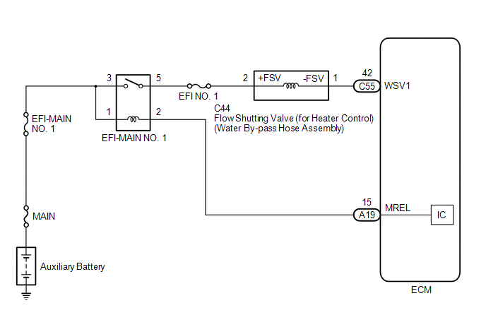
NOTICE:
- Inspect the fuses for circuits related to this system before performing the following procedure.
- Vehicle Control History may be stored in the hybrid vehicle control ECU assembly if the engine is malfunctioning. Certain vehicle condition information is recorded when Vehicle Control History is stored. Reading the vehicle conditions recorded in both the freeze frame data and Vehicle Control History can be useful for troubleshooting.
Click here

(Select Powertrain in Health Check and then check the time stamp data.)
Click here
- If any "Engine Malfunction" Vehicle Control History item has been stored in the hybrid vehicle control ECU assembly, make sure to clear it. However, as all Vehicle Control History items are cleared simultaneously, if any Vehicle Control History items other than "Engine Malfunction" are stored, make sure to perform any troubleshooting for them before clearing Vehicle Control History.
Click here
HINT:
Read Freeze Frame Data using the Techstream. The ECM records vehicle and driving condition information as Freeze Frame Data the moment a DTC is stored. When troubleshooting, Freeze Frame Data can help determine if the vehicle was moving or stationary, if the engine was warmed up or not, if the air fuel ratio was lean or rich, and other data from the time the malfunction occurred.
PROCEDURE
CHECK TERMINAL VOLTAGE (POWER SOURCE OF FLOW SHUTTING VALVE (FOR HEATER CONTROL))
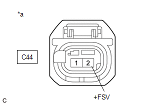
*a |
Front view of wire harness connector (to Flow Shutting Valve (for Heater Control) (Water By-pass Hose Assembly)) |
(a) Disconnect the flow shutting valve (for heater control) (water by-pass hose assembly) connector.
(b) Turn the power switch on (IG).
(c) Measure the voltage according to the value(s) in the table below.
Standard Voltage:
Tester Connection | Condition | Specified Condition |
|---|---|---|
C44-2 (+FSV) - Body ground |
Power switch on (IG) |
11 to 14 V |
| NG |  |
REPAIR OR REPLACE HARNESS OR CONNECTOR (EFI-MAIN NO. 1 RELAY - FLOW SHUTTING VALVE (FOR HEATER CONTROL)) |
|

INSPECT FLOW SHUTTING VALVE (FOR HEATER CONTROL) (WATER BY-PASS HOSE ASSEMBLY)
(a) Inspect the flow shutting valve (for heater control) (water by-pass hose assembly).
Click here
| NG | |
REPLACE FLOW SHUTTING VALVE (FOR HEATER CONTROL) (WATER BY-PASS HOSE ASSEMBLY) |
|
CHECK HARNESS AND CONNECTOR (FLOW SHUTTING VALVE (FOR HEATER CONTROL) - ECM)
(a) Disconnect the flow shutting valve (for heater control) (water by-pass hose assembly) connector.
(b) Disconnect the ECM connector.
(c) Measure the resistance according to the value(s) in the table below.
Standard Resistance:
Tester Connection | Condition | Specified Condition |
|---|---|---|
C44-1 (-FSV) - C55-42 (WSV1) |
Always |
Below 1 Ω |
C44-1 (-FSV) or C55-42 (WSV1) - Body ground and other terminals |
Always |
10 kΩ or higher |
| OK | |
REPLACE ECM |
| NG | |
REPAIR OR REPLACE HARNESS OR CONNECTOR |
Poor Engine Power (P319000,P319100)
DESCRIPTION
The ECM receives signals from the hybrid vehicle control ECU assembly such as the requested engine torque, target engine speed and engine cranking status, and controls the engine output based on the target engine speed and requested torque.
DTC No. | Detection Item | DTC Detection Condition | Trouble Area | MIL | Memory | Note |
|---|---|---|---|---|---|---|
P319000 |
Poor Engine Power |
When all of the following conditions are met (1 trip detection logic):
|
|
Comes on |
DTC stored |
SAE Code: P3190 |
P319100 |
Engine does not Start |
When all of the following conditions are met (1 trip detection logic):
|
|
Comes on |
DTC stored |
SAE Code: P3191 |
MONITOR DESCRIPTION
- The ECM receives signals such as requested engine torque, target engine speed and engine cranking status from the hybrid vehicle control ECU assembly.
- The ECM controls engine start and stop and the throttle valve angle based on the signals received from the hybrid vehicle control ECU assembly.
- The ECM receives the actual engine torque calculated by the hybrid vehicle control ECU assembly based on the generator torque.
- When the actual engine torque is less than 20% of the requested engine torque*, the ECM judges that the engine output is abnormal and stores DTC P319000.
(The engine may not have started in the above situation.)
- *: Requested torque = Requested Engine Torque (kW) / HV Target Engine Speed (rpm) x 9549
- If the ECM does not detect engine start torque (actual engine torque) even though it has received an engine start request and started the engine, it stores DTC P319100.
HINT:
- When DTCs P319000, P319100 and P319300 are output, the engine may be stopped due to the engine condition.
At this time, after adding fuel or performing repairs, clear the DTCs. Then turn the power switch off to return to the normal condition.
- When this DTC is output and the engine is stopped, the HV battery cannot be charged since the vehicle is driven with the motor only. If the vehicle continues to be driven under this condition, the HV battery will become depleted and the power switch will not be able to be turned on (READY).
- When DTC P319000 or P319100 is stored, the engine torque has dropped by 80% or the engine cannot be started. If any DTCs that indicate malfunctioning of engine related parts are stored at the same time, repair the malfunctioning parts first.
- If engine knock is detected due to mechanical noise or a knock control sensor being loose, the ignition timing (Knock F/B Value, Knock Correct Learn Value) may be excessively retarded and DTC P319000 may be stored.
Relevant Data List Items:
ECM (Powertrain / Engine / Data List)
HV Target Engine Speed
Engine Speed
Requested Engine Torque
Actual Engine Torque
Throttle Position Command
Throttle Position Sensor No.1 Voltage
Calculate Load
Coolant Temperature
Short FT B1S1
Long FT B1S1
Target EGR Valve Position No.1
Ignition Timing Cylinder #1
Knock F/B Value
Knock Correct Learn Value
-
-
Hybrid Vehicle Control ECU (Powertrain / Hybrid Control / Data List)
Target Engine Revolution
Engine Speed
Target Engine Power
Coolant Temperature
Engine Idling Request
-
-
-
- When DTCs P319000, P319100 and P319300 are output, the engine may be stopped due to the engine condition.
MONITOR STRATEGY
Related DTCs |
P3190: Poor engine power P3191: Engine does not start |
Required Sensors/Components (Main) |
Crankshaft position sensor |
Required Sensors/Components (Related) |
Hybrid vehicle control ECU assembly |
Frequency of Operation |
Continuous |
Duration |
100 engine revolutions or 6 seconds |
MIL Operation |
Immediate |
Sequence of Operation |
None |
TYPICAL ENABLING CONDITIONS
P3190 and P3191Monitor runs whenever the following DTCs are not stored |
None |
Fuel cut operation |
Not operated |
Engine speed |
650 rpm or more (varies with engine coolant temperature) |
Communication with hybrid vehicle control ECU assembly |
No malfunction |
TYPICAL MALFUNCTION THRESHOLDS
P3190Time for low engine torque |
100 engine revolutions or more, and 6 seconds or more (varies with engine coolant temperature) |
Fuel level |
Not empty |
Ratio of estimated torque against target torque |
Less than 20% |
Engine start no-determination time (receive from hybrid vehicle control ECU) |
100 engine revolutions or more, and 6 seconds or more (varies with engine coolant temperature) |
Fuel level |
Not empty |
Engine speed is a fixed value or more |
- |
CONFIRMATION DRIVING PATTERN
NOTICE:
If the MIL or a master warning light illuminates, immediately end the confirmation driving pattern. If DTCs P319000, P319100 and P319300 are output and the engine is stopped, the HV battery will no longer be chargeable and the distance that the vehicle can be driven will be limited.
HINT:
- After repair has been completed, clear the DTC and then check that the vehicle has returned to normal by performing the following All Readiness check procedure.
Click here

- When clearing the permanent DTCs, refer to the "CLEAR PERMANENT DTC" procedure.
Click here
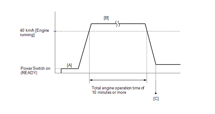
- Apply the parking brake firmly.
- Connect the Techstream to the DLC3.
- Turn the power switch on (IG).
- Turn the Techstream on.
- Clear the DTCs (even if no DTCs are stored, perform the clear DTC procedure).
- Turn the power switch off and wait for at least 30 seconds.
- Turn the power switch on (READY).
- Turn the Techstream on.
- Fully depress the accelerator pedal for 10 seconds with the vehicle stopped, the shift lever in P and the brake pedal depressed [A].
NOTICE:
As soon as the engine starts, release the accelerator pedal.
- Release the parking brake.
- Drive the vehicle at an average of approximately 40 km/h or more until the total engine operation time is 10 minutes or more [B].
CAUTION:
When performing the confirmation driving pattern, obey all speed limits and traffic laws.
HINT:
- It is not necessary to maintain the vehicle speed at 40 km/h throughout the road test.
- If the engine stops, further depress the accelerator pedal to restart the engine.
- Enter the following menus: Powertrain / Engine / Trouble Codes [C].
- Read the pending DTCs.
HINT:
- If a pending DTC is output, the system is malfunctioning.
- If a pending DTC is not output, perform the following procedure.
- Enter the following menus: Powertrain / Engine / Utility / All Readiness.
- Input the DTC: P319000 or P319100.
- Check the DTC judgment result.
Techstream Display
Description
NORMAL
- DTC judgment completed
- System normal
ABNORMAL
- DTC judgment completed
- System abnormal
INCOMPLETE
- DTC judgment not completed
- Perform driving pattern after confirming DTC enabling conditions
HINT:
- If the judgment result shows NORMAL, the system is normal.
- If the judgment result shows ABNORMAL, the system is malfunctioning.
- If the judgment result shows INCOMPLETE, perform the Confirmation Driving Pattern and check the DTC judgment result again.
- [A] to [C]: Normal judgment procedure.
The normal judgment procedure is used to complete DTC judgment and also used when clearing permanent DTCs.
- When clearing the permanent DTCs, do not disconnect the cable from the auxiliary battery terminal or attempt to clear the DTCs during this procedure, as doing so will clear the universal trip and normal judgment histories.
NOTICE:
- Vehicle Control History may be stored in the hybrid vehicle control ECU assembly if the engine is malfunctioning. Certain vehicle condition information is recorded when Vehicle Control History is stored. Reading the vehicle conditions recorded in both the Freeze Frame Data and Vehicle Control History can be useful for troubleshooting.
Click here
(Select Powertrain in Health Check and then check the time stamp data.)
Click here
- If any "Engine Malfunction" Vehicle Control History item has been stored in the hybrid vehicle control ECU assembly, make sure to clear it. However, as all Vehicle Control History items are cleared simultaneously, if any Vehicle Control History items other than "Engine Malfunction" are stored, make sure to perform any troubleshooting for them before clearing Vehicle Control History.
Click here
HINT:
- Performing this diagnosis procedure repeatedly for symptom confirmation may cause the SOC to drop, preventing the system from entering the READY-on state. In this case, use the THS charger to charge the HV battery.
- Cranking the engine once causes the SOC to drop approximately 1%.
- Charging the HV battery once (10 minutes) using the THS charger restores the SOC approximately 2%.
- Charging the HV battery using the THS charger takes approximately 10 minutes when the HV battery temperature is 25 °C or approximately 30 minutes when the HV battery temperature is 0 °C.
- The THS charger is a supplemental charging device that charges the HV battery enough to enable the engine to start (the vehicle can enter the READY-on state).
- Read Freeze Frame Data using the Techstream. The ECM records vehicle and driving condition information as Freeze Frame Data the moment a DTC is stored. When troubleshooting, freeze frame data can help determine if the vehicle was moving or stationary, if the engine was warmed up or not, if the air fuel ratio was lean or rich, and other data from the time the malfunction occurred.
PROCEDURE
CHECK ANY OTHER DTCS OUTPUT (IN ADDITION TO DTC P319000, P319100 AND/OR P319300)
(a) Connect the Techstream to the DLC3.
(b) Turn the power switch on (IG).
(c) Turn the Techstream on.
(d) Enter the following menus: Powertrain / Engine / Trouble Codes.
(e) Check for DTCs and freeze frame data and write them down.
Powertrain > Engine > Trouble CodesResult | Proceed to |
|---|---|
DTC P319000 or P319100 are output |
A |
DTC P319300 is output |
B |
DTC P319000, P319100 and/or P319300 and other DTCs are output |
C |
HINT:
If any SFI system DTCs other than DTC P319000, P319100 or P319300 are output, perform troubleshooting for those DTCs first.
| B |  |
GO TO DTC P319300 |
| C | |
GO TO DTC CHART |
|

CHECK SHORTAGE OF FUEL
(a) Check the amount of fuel remaining.
OK:
There is enough fuel.
HINT:
- DTCs P319000, P319100 and/or P319300 may be output if the vehicle ran out of fuel in the past.
- If not enough fuel is added, DTC P319000, P319100 or P319300 may be output again. If the engine cannot be started because the vehicle is out of fuel, add fuel until the fuel level warning turns off.
| NG | |
REFILL FUEL |
|
CLEAR DTC
(a) Connect the Techstream to the DLC3.
(b) Turn the power switch on (IG).
(c) Turn the Techstream on.
(d) Clear the DTCs.
Powertrain > Engine > Clear DTCs(e) Turn the power switch off and wait for at least 30 seconds.
|
CHECK PCV VALVE AND HOSE CONNECTIONS
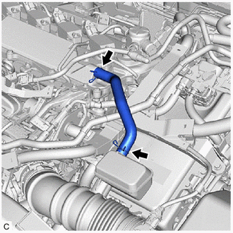
(a) Check the PCV hose connections.
(b) Check the PCV valve.
Click here
OK:
PCV hose and PCV valve are connected correctly and are not damaged.
| NG | |
REPAIR OR REPLACE PCV VALVE OR HOSE |
|
CHECK INTAKE SYSTEM
(a) Check the intake system for vacuum leaks.
Click here
OK:
No leaks from intake system.
HINT:
Perform "Inspection After Repair" after repairing or replacing the intake system.
Click here
| NG | |
REPAIR OR REPLACE INTAKE SYSTEM |
|
CHECK FOR UNUSUAL NOISE OR VIBRATION WHEN STARTING ENGINE OR REVVING
OK:
Unusual noise and vibration do not occur.
| NG | |
REPAIR OR REPLACE MALFUNCTIONING PARTS |
|
CHECK FUEL PRESSURE (FOR LOW PRESSURE SIDE)
(a) Check the fuel pressure (for low pressure side).
Click here
HINT:
Perform "Inspection After Repair" after replacing the fuel pump (for low pressure side).
Click here
| NG | |
REPLACE FUEL PUMP (FOR LOW PRESSURE SIDE) |
|
INSPECT THROTTLE BODY WITH MOTOR ASSEMBLY
(a) Inspect the throttle body with motor assembly.
Click here
HINT:
Perform "Inspection After Repair" after replacing the throttle body with motor assembly.
Click here
| NG | |
REPLACE THROTTLE BODY WITH MOTOR ASSEMBLY |
|
INSPECT MASS AIR FLOW METER SUB-ASSEMBLY
(a) Inspect the mass air flow meter sub-assembly, referring to On-vehicle Inspection for Mass Air Flow Meter.
Click here
(b) Inspect the mass air flow meter sub-assembly, referring to Inspection for Mass Air Flow Meter.
Click here
HINT:
Perform "Inspection After Repair" after replacing the mass air flow meter sub-assembly.
Click here
| NG | |
REPLACE MASS AIR FLOW METER SUB-ASSEMBLY |
|
INSPECT ENGINE COOLANT TEMPERATURE SENSOR
(a) Inspect the engine coolant temperature sensor.
Click here
HINT:
Perform "Inspection After Repair" after replacing the engine coolant temperature sensor.
Click here
| NG | |
REPLACE ENGINE COOLANT TEMPERATURE SENSOR |
|
PERFORM ACTIVE TEST USING TECHSTREAM (CONTROL THE EGR STEP POSITION)
(a) Connect the Techstream to the DLC3.
(b) Turn the power switch on (IG).
(c) Turn the Techstream on.
(d) Put the engine in Inspection Mode (Maintenance Mode).
Powertrain > Hybrid Control > UtilityInspection Mode
(e) Start the engine and warm it up until the engine coolant temperature is 75 °C or higher.
HINT:
The A/C switch and all accessories should be off.
(f) Enter the following menus: Powertrain / Engine / Active Test / Control the EGR Step Position / Data List / Intake Manifold Absolute Pressure, Coolant Temperature and Engine Independent.
Powertrain > Engine > Active TestControl the EGR Step Position
Data List Display |
|---|
Intake Manifold Absolute Pressure |
Coolant Temperature |
Engine Independent |
(g) Confirm that the value of Data List item Engine Independent is "Operate" then check the value of Intake Manifold Absolute Pressure while performing the Active Test.
NOTICE:
- Make sure that the value of Data List item Engine Independent is "Operate" while performing the Active Test.
- Do not leave the EGR valve open for 10 seconds or more during the Active Test.
- Be sure to return the EGR valve to step 0 when the Active Test is completed.
- Do not open the EGR valve 30 steps or more during the Active Test.
OK:
The value of Intake Manifold Absolute Pressure changes in response to the EGR step position when the value of Engine Independent is "Operate".
Standard:
- | Control the EGR Step Position (Active Test) |
|
|---|---|---|
0 Steps | 0 to 30 Steps |
|
Intake Manifold Absolute Pressure (Data List) |
(EGR valve is fully closed) |
Intake Manifold Absolute Pressure value is at least +10 kPa (1.45 psi) higher than when EGR valve is fully closed |
HINT:
- If the value of Data List item Engine Independent is "Not Opr" when the engine is idling, charge control is being performed. Perform the Active Test after charge control is complete ("Operate" is displayed).
- While performing the Active Test, if the increase in the value of Intake Manifold Absolute Pressure is small, the EGR valve assembly may be malfunctioning.
- Even if the EGR valve assembly is malfunctioning, rough idling or an increase in the value of Intake Manifold Absolute Pressure may occur while performing the Active Test. However, the amount that the value of Intake Manifold Absolute Pressure increases will be smaller than normal.
- If the Active Test cannot be performed due to a malfunction such as the engine not starting, perform the EGR valve assembly inspection the following step.
| OK | |
GO TO STEP 13 |
|
INSPECT EGR VALVE ASSEMBLY
(a) Remove the EGR valve assembly.
Click here
(b) Check if the EGR valve is stuck open.
OK:
EGR valve is tightly closed.
HINT:
Perform "Inspection After Repair" after replacing the EGR valve assembly.
Click here
| NG | |
REPLACE EGR VALVE ASSEMBLY |
|
REPLACE CRANKSHAFT POSITION SENSOR
(a) Replace the crankshaft position sensor.
Click here
|
CLEAR DTC
(a) Connect the Techstream to the DLC3.
(b) Turn the power switch on (IG).
(c) Turn the Techstream on.
(d) Clear the DTCs.
Powertrain > Engine > Clear DTCs(e) Turn the power switch off and wait for at least 30 seconds.
|
CHECK WHETHER DTC OUTPUT RECURS (DTC P319000 OR P319100)
(a) Drive the vehicle in accordance with the driving pattern described in Confirmation Driving Pattern.
(b) Enter the following menus: Powertrain / Engine / Trouble Codes.
(c) Read the DTCs.
Powertrain > Engine > Trouble CodesResult | Proceed to |
|---|---|
DTCs are not output |
A |
DTC P319000 or P319100 is output |
B |
| A | |
END |
|
REPLACE CAMSHAFT POSITION SENSOR (FOR INTAKE CAMSHAFT)
(a) Replace the camshaft position sensor (for intake camshaft).
Click here
|
CLEAR DTC
(a) Connect the Techstream to the DLC3.
(b) Turn the power switch on (IG).
(c) Turn the Techstream on.
(d) Clear the DTCs.
Powertrain > Engine > Clear DTCs(e) Turn the power switch off and wait for at least 30 seconds.
|
CHECK WHETHER DTC OUTPUT RECURS (DTC P319000 OR P319100)
(a) Drive the vehicle in accordance with the driving pattern described in Confirmation Driving Pattern.
(b) Enter the following menus: Powertrain / Engine / Trouble Codes.
(c) Read the DTCs.
Powertrain > Engine > Trouble CodesResult | Proceed to |
|---|---|
DTCs are not output |
A |
DTC P319000 or P319100 is output |
B |
| A | |
END |
|
REPLACE CAMSHAFT POSITION SENSOR (FOR EXHAUST CAMSHAFT)
(a) Replace the camshaft position sensor (for exhaust camshaft).
Click here
|
CLEAR DTC
(a) Connect the Techstream to the DLC3.
(b) Turn the power switch on (IG).
(c) Turn the Techstream on.
(d) Clear the DTCs.
Powertrain > Engine > Clear DTCs(e) Turn the power switch off and wait for at least 30 seconds.
|
CHECK WHETHER DTC OUTPUT RECURS (DTC P319000 OR P319100)
(a) Drive the vehicle in accordance with the driving pattern described in Confirmation Driving Pattern.
(b) Enter the following menus: Powertrain / Engine / Trouble Codes.
(c) Read the DTCs.
Powertrain > Engine > Trouble CodesResult | Proceed to |
|---|---|
DTCs are not output |
A |
DTC P319000 or P319100 is output |
B |
| A | |
END |
|
REPLACE ECM
(a) Replace the ECM.
Click here
|
CLEAR DTC
(a) Connect the Techstream to the DLC3.
(b) Turn the power switch on (IG).
(c) Turn the Techstream on.
(d) Clear the DTCs.
Powertrain > Engine > Clear DTCs(e) Turn the power switch off and wait for at least 30 seconds.
|
CONFIRM WHETHER MALFUNCTION HAS BEEN SUCCESSFULLY REPAIRED
(a) Drive the vehicle in accordance with the driving pattern described in Confirmation Driving Pattern.
(b) Enter the following menus: Powertrain / Engine / Trouble Codes.
(c) Read the DTCs.
Powertrain > Engine > Trouble Codes| NEXT | |
END |