Thermostat
Components
COMPONENTS
ILLUSTRATION
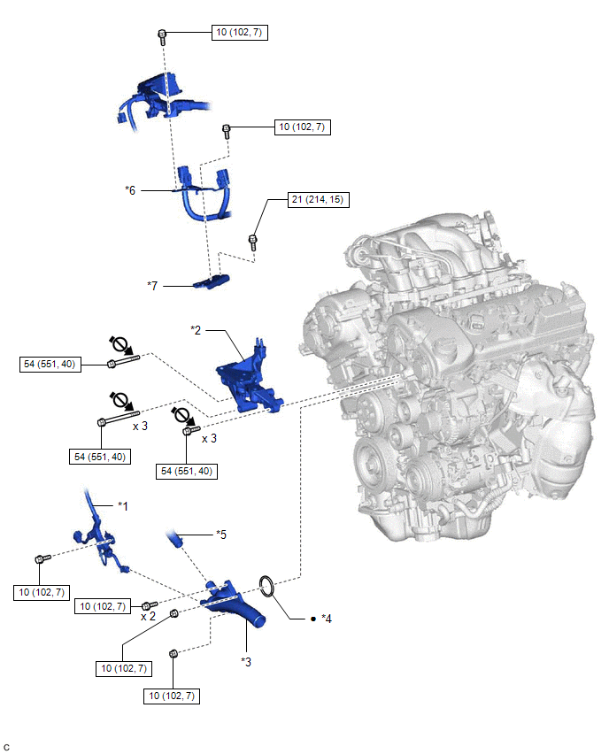
*1 |
ENGINE WIRE |
*2 |
FRONT NO. 1 ENGINE MOUNTING BRACKET LH |
*3 |
WATER INLET WITH THERMOSTAT SUB-ASSEMBLY |
*4 |
GASKET |
*5 |
WATER BY-PASS HOSE |
*6 |
WIRE HARNESS CLAMP BRACKET |
*7 |
NO. 2 ENGINE MOUNTING STAY RH |
- |
- |
 |
N*m (kgf*cm, ft.*lbf): Specified torque |
● |
Non-reusable part |
 |
Do not apply lubricants to the threaded parts |
- |
- |
Inspection
INSPECTION
PROCEDURE
1. INSPECT WATER INLET WITH THERMOSTAT SUB-ASSEMBLY
(a) Check the valve opening.
HINT:
The valve opening temperature is inscribed on the water inlet with thermostat sub-assembly.
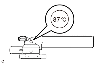
(1) Add 15 cc (0.9 cu. in.) of water to the water inlet with thermostat sub-assembly from the inlet pipe side. |
|
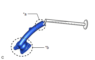
(2) Confirm that water does not flow out from the valve side of the water inlet with thermostat sub-assembly.
If water flows out from the valve side of the water inlet with thermostat sub-assembly, replace the water inlet with thermostat sub-assembly with a new one.
(3) Immerse the water inlet with thermostat sub-assembly in water that is between 92 °C and 96 °C for 5 minutes or more.
NOTICE:
- Do not allow any water to come into contact with the connector of the water inlet with thermostat sub-assembly.
- Make sure that the end of the inlet pipe of the water inlet with thermostat sub-assembly is not facing downward.
- Make sure to immerse the water inlet with thermostat sub-assembly in the water as shown in the illustration.
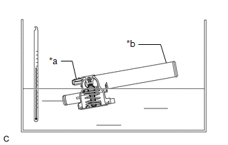
*a |
Connector |
*b |
Inlet Pipe |
 |
Temperature Sensor |
(4) Leave the water inlet with thermostat sub-assembly at ambient temperature for 5 minutes so that the valve closes. NOTICE: Make sure that the end of the inlet pipe of the water inlet with thermostat sub-assembly is not facing downward. |
|
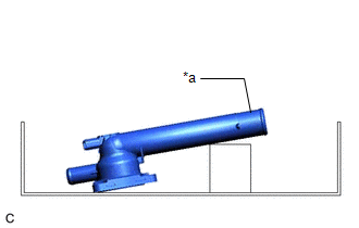
(5) Check that the water that was added to the water inlet with thermostat sub-assembly has completely flowed out.
If the water that was added to the water inlet with thermostat sub-assembly has not completely flowed out, replace the water inlet with thermostat sub-assembly with a new one.
(b) Check the resistance of the temperature sensor.
(1) Measure the resistance according to the value(s) in the table below.
Standard Resistance:
Tester Connection | Condition | Specified Condition |
|---|---|---|
1 - 2 |
Always |
10.6 to 14.2 Ω |
If the result is not as specified, replace the water inlet with thermostat sub-assembly.
Installation
INSTALLATION
PROCEDURE
1. INSTALL WATER INLET WITH THERMOSTAT SUB-ASSEMBLY
(a) Install a new gasket to the water inlet with thermostat sub-assembly.
(b) Install the water inlet with thermostat sub-assembly with the 2 bolts and 2 nuts.
Torque:
10 N·m {102 kgf·cm, 7 ft·lbf}
2. CONNECT WATER BY-PASS HOSE
(a) Connect the water by-pass hose and slide the clip to secure it.
3. INSTALL FRONT NO. 1 ENGINE MOUNTING BRACKET LH
Click here 
4. CONNECT ENGINE WIRE
(a) Engage the clamp to connect the engine wire.
(b) Install the bolt.
Torque:
10 N·m {102 kgf·cm, 7 ft·lbf}
(c) Connect the water inlet with thermostat sub-assembly connector.
5. INSTALL NO. 2 ENGINE MOUNTING STAY RH
(a) Install the No. 2 engine mounting stay RH to the intake manifold and front No. 1 engine mounting bracket LH with the bolt.
Torque:
21 N·m {214 kgf·cm, 15 ft·lbf}
(b) Connect the wire harness clamp bracket to the No. 2 engine mounting stay RH with the bolt.
Torque:
10 N·m {102 kgf·cm, 7 ft·lbf}
(c) Connect the wire harness clamp to the wire harness clamp bracket with the bolt.
Torque:
10 N·m {102 kgf·cm, 7 ft·lbf}
6. INSTALL ENGINE ASSEMBLY WITH TRANSAXLE
Click here
Removal
REMOVAL
The necessary procedures (adjustment, calibration, initialization or registration) that must be performed after parts are removed and installed, or replaced during water inlet with thermostat sub-assembly removal/installation are shown below.
Necessary Procedure After Parts Removed/Installed/ReplacedReplaced Part or Performed Procedure | Necessary Procedure | Effect/Inoperative Function when Necessary Procedure not Performed | Link |
|---|---|---|---|
Battery terminal is disconnected/reconnected |
Perform steering sensor zero point calibration |
Lane departure alert system (w/ Steering Control) |
 |
Pre-collision system |
|||
Intelligent Clearance Sonar System*1 |
|||
Lighting System (for Gasoline Model with Cornering Light) |
|||
Memorize steering angle neutral point |
Parking Assist Monitor System |
|
|
Panoramic View Monitor System |
|
||
Replacement of ECM |
Vehicle Identification Number (VIN) registration |
MIL comes on |
|
ECU communication ID registration (Immobiliser system) |
Engine start function |
|
|
|
Inspection after repair |
|
|
Replacement of automatic transaxle assembly |
|
|
|
Replacement of ECM (If transaxle compensation code read from ECM) |
|
||
Replacement of ECM (If transaxle compensation code not read from ECM) |
|
||
Replacement of automatic transaxle fluid |
ATF thermal degradation estimate reset |
The value of the Data List item "ATF Thermal Degradation Estimate" is not estimated correctly |
|
Replacement of ECM |
Code registration (Smart Key System (for Start Function)) |
|
|
Suspension, tires, etc. |
|
|
|
Rear television camera assembly optical axis adjustment (Back camera position setting) |
Parking Assist Monitor System |
|
|
|
Panoramic View Monitor System |
|
|
Perform headlight ECU sub-assembly LH initialization |
Lighting system (for Gasoline Model with Cornering Light) |
|
|
Front wheel alignment adjustment |
Perform system variant learning and acceleration sensor zero point calibration. |
|
|
- *1: When performing learning using the Techstream.
Click here
- *2: Not necessary when ECM replaced with new one.
PROCEDURE
1. REMOVE ENGINE ASSEMBLY WITH TRANSAXLE
Click here
2. REMOVE NO. 2 ENGINE MOUNTING STAY RH
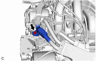
(a) Remove the bolt and disconnect the wire harness clamp from the wire harness clamp bracket. |
 |
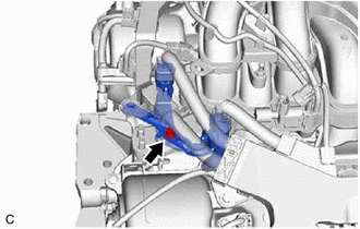
(b) Remove the bolt and separate the wire harness clamp bracket from the No. 2 engine mounting stay RH. |
 |
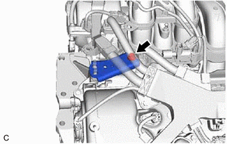
(c) Remove the bolt and No. 2 engine mounting stay RH from the intake manifold and front No. 1 engine mounting bracket LH. |
 |
3. DISCONNECT ENGINE WIRE
(a) Disconnect the water inlet with thermostat sub-assembly connector. |
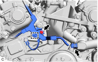 |
(b) Remove the bolt.
(c) Disengage the clamp to disconnect the engine wire.
4. REMOVE FRONT NO. 1 ENGINE MOUNTING BRACKET LH
Click here
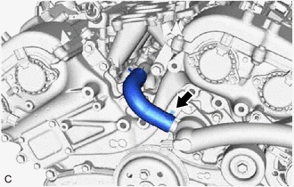
5. DISCONNECT WATER BY-PASS HOSE
(a) Slide the clip and disconnect the water by-pass hose. |
 |
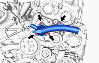
6. REMOVE WATER INLET WITH THERMOSTAT SUB-ASSEMBLY
(a) Remove the 2 bolts, 2 nuts and water inlet with thermostat sub-assembly. |
 |
(b) Remove the gasket from the water inlet with thermostat sub-assembly.