Problem Symptoms Table. Shift Paddle Switch Circuit. Shut Down Signal Circuit
Problem Symptoms Table
PROBLEM SYMPTOMS TABLE
Hybrid Control SystemSymptom | Suspected Area | Link |
|---|---|---|
Cannot enter EV drive mode |
CAN Communication System |
 |
Pattern Select Switch EV Mode Circuit |
|
|
EV drive mode switch (Electric parking brake switch assembly) |
|
|
Combination meter assembly |
|
|
EV mode indicator light does not illuminate |
Combination meter assembly |
|
EV drive mode switch (Electric parking brake switch assembly) |
|
|
Pattern Select Switch EV Mode Circuit |
|
|
EV mode indicator light does not turn off |
Combination meter assembly |
|
EV drive mode switch (Electric parking brake switch assembly) |
|
|
Pattern Select Switch EV Mode Circuit |
|
|
Cannot enter ECO mode |
CAN Communication System |
|
ECO mode switch (Electric parking brake switch assembly) |
|
|
Pattern Select Switch ECO Mode Circuit |
|
|
Combination meter assembly |
|
|
ECO mode indicator light does not illuminate |
ECO mode switch (Electric parking brake switch assembly) |
|
Pattern Select Switch ECO Mode Circuit |
|
|
Combination meter assembly |
|
|
ECO mode indicator light does not turn off |
ECO mode switch (Electric parking brake switch assembly) |
|
Pattern Select Switch ECO Mode Circuit |
|
|
Combination meter assembly |
|
|
Cannot enter SPORT mode |
CAN Communication System |
|
SPORT mode switch (Electric parking brake switch assembly) |
|
|
Pattern Select Switch SPORT Mode Circuit |
|
|
Combination meter assembly |
|
|
SPORT mode indicator light does not illuminate |
SPORT mode switch (Electric parking brake switch assembly) |
|
Pattern Select Switch SPORT Mode Circuit |
|
|
Combination meter assembly |
|
|
SPORT mode indicator light does not turn off |
SPORT mode switch (Electric parking brake switch assembly) |
|
Pattern Select Switch SPORT Mode Circuit |
|
|
Combination meter assembly |
|
|
Hunting (Poor idle) |
Check for Diagnosis Related Information*3 |
|
Drive Start Control |
|
|
Hesitation and/or poor acceleration |
Check for Diagnosis Related Information*3 |
|
Brake Override System |
|
|
Drive Start Control |
|
|
Shift range position cannot be changed by shifting to "+" or "-" |
Transmission Control Switch Circuit |
|
Shift Paddle Switch Circuit |
|
|
Shift position indicator is malfunctioning |
Indicator Circuit |
|
Power switch does not turn on (READY). |
Check Vehicle Control History (wrong assembly confirmation)*1 |
|
Smart Key System (for start function) |
|
|
ECU Power Source Circuit (Hybrid control system) |
|
|
Hybrid vehicle control ECU |
|
|
ECM |
|
|
Loud rattle from hybrid vehicle transaxle |
Check idle learning |
|
Transmission input damper assembly |
|
|
Hybrid vehicle transaxle assembly |
|
|
Engine misfire |
- |
|
"Maintenance Required for Traction Battery Cooling Parts See Owner's Manual" is displayed on the multi-information display. *2 |
1. Make sure the HV battery cooling system intake port is not blocked. |
- |
2. Make sure there are no gaps between the connecting parts of the ducts. |
- |
|
3. Clean the No. 1 hybrid battery intake filter. Check for entry of foreign matter. |
|
|
4. Clear the DTCs to reset the learning values even if no DTCs are stored. |
|
|
Abnormal sound is heard from the area around the No. 1 hybrid battery intake duct. |
1. Make sure the HV battery cooling system intake port is not blocked. |
- |
2. Make sure there are no gaps between the connecting parts of the ducts. |
- |
|
3. Clean the No. 1 hybrid battery intake filter. Check for entry of foreign matter. |
|
|
4. Clear the DTCs to reset the learning values even if no DTCs are stored. |
|
|
Engine stops and starts less frequently. |
Check Vehicle Control History (Limit to Charge / Discharge Control Value by Hybrid Battery Temperature High) |
|
Engine speed returns to idle slowly after accelerator pedal is fully released. |
Check Vehicle Control History (Limit to Charge / Discharge Control Value by Hybrid Battery Temperature High) |
|
*1: Check Vehicle Control History (wrong assembly confirmation)
- Using the Techstream, check the vehicle control history.
Click here
HINT:
If "Hybrid Battery Pack Sensor Module Mismatch" is displayed, the wrong type of battery voltage sensor is installed.
- If the battery voltage sensor had been replaced just before the malfunction occurred, check the part number of the battery voltage sensor.
HINT:
- The type of battery voltage sensor to be used varies depending on the vehicle model.
- If the wrong type of battery voltage sensor is installed, the power switch cannot be turned on (READY).
- After installing the battery voltage sensor, perform the following to check that the power switch can be turned on (READY).
- Turn the power switch on (READY).
- Turn the power switch off and wait for 2 minutes or more.
- Turn the power switch on (READY) again.
*2: If the battery cooling blower assembly malfunctions, DTC P0A8100, P0A8111, P0A8115, P0A814B, P0A8196 or P0A8198 will be stored. If only "Maintenance Required for Traction Battery Cooling Parts See Owner's Manual" is displayed on the multi-information display, only perform the inspection of the HV battery cooling system intake port, filter and duct.
*3: If any of the following Diagnosis Related Information items are output, perform troubleshooting for the corresponding DTCs.
ResultResult | Link |
|
|---|---|---|
Hybrid control system |
P312387 |
|
Motor generator control system |
P31241F |
|
P312487 |
||
Shift Paddle Switch Circuit
DESCRIPTION
Moving the shift lever to S enables the shift range to be selected. The shift range can be selected by operating the "+" or "-" shift paddle switch.
WIRING DIAGRAM
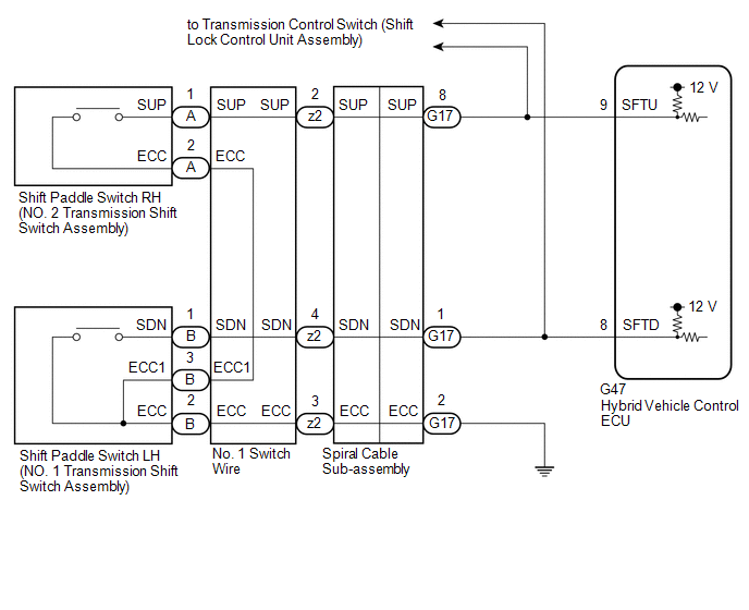
NOTICE:
After turning the power switch off, waiting time may be required before disconnecting the cable from the negative (-) auxiliary battery terminal. Therefore, make sure to read the disconnecting the cable from the negative (-) auxiliary battery terminal notices before proceeding with work.
Click here 
PROCEDURE
READ VALUE USING TECHSTREAM (SPORTS SHIFT UP SIGNAL, SPORTS SHIFT DOWN SIGNAL)
(a) Connect the Techstream to the DLC3.
(b) Turn the power switch on (IG).
(c) Enter the following menus: Powertrain / Hybrid Control / Data List / Sports Shift UP Signal, Sports Shift DOWN Signal.
Powertrain > Hybrid Control > Data ListTester Display |
|---|
Sports Shift UP Signal |
Sports Shift DOWN Signal |
(d) Read the values displayed on the Techstream.
Powertrain > Hybrid Control > Data ListTester Display | Measurement Item | Range | Normal Condition |
|---|---|---|---|
Sports Shift UP Signal |
Sport shift up switch status |
ON or OFF |
Shift paddle switch RH (+) operated: ON Shift paddle switch RH (+) not operated: OFF |
Sports Shift DOWN Signal |
Sport shift down switch status |
ON or OFF |
Shift paddle switch LH (-) operated: ON Shift paddle switch LH (-) not operated: OFF |
Result | Proceed to |
|---|---|
The Techstream display changes according to the shift paddle switch (transmission shift switch assembly) operation |
A |
The Techstream display does not change according to the shift paddle switch (transmission shift switch assembly) operation |
B |
(e) Turn the power switch off.
| A |  |
CHECK FOR INTERMITTENT PROBLEMS |
|

CHECK HARNESS AND CONNECTOR (SHIFT PADDLE SWITCH CIRCUIT)
(a) Disconnect the G47 hybrid vehicle control ECU connector.
(b) Disconnect the G22 transmission control switch (shift lock control unit assembly) connector.
(c) Measure the resistance according to the value(s) in the table below. Standard Resistance:
|
|
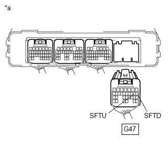
(d) Reconnect the G22 transmission control switch (shift lock control unit assembly) connector.
(e) Reconnect the G47 hybrid vehicle control ECU connector.
| OK | |
REPLACE HYBRID VEHICLE CONTROL ECU |
|
CHECK HARNESS AND CONNECTOR (SPIRAL CABLE SUB-ASSEMBLY - BODY GROUND)
(a) Disconnect the G17 spiral cable sub-assembly connector. |
|
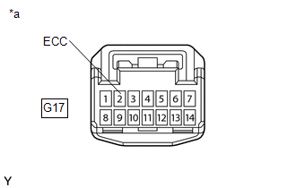
(b) Measure the resistance according to the value(s) in the table below.
Standard Resistance (Open):
Tester Connection | Condition | Specified Condition |
|---|---|---|
G17-2 (ECC) - Body ground |
Always |
Below 1 Ω |
(c) Reconnect the G17 spiral cable sub-assembly connector.
| NG | |
REPAIR OR REPLACE HARNESS OR CONNECTOR |
|
CHECK HARNESS AND CONNECTOR (SPIRAL CABLE SUB-ASSEMBLY - HYBRID VEHICLE CONTROL ECU)
(a) Disconnect the G47 hybrid vehicle control ECU connector.
(b) Disconnect the G17 spiral cable sub-assembly connector.
(c) Measure the resistance according to the value(s) in the table below. Standard Resistance:
|
|
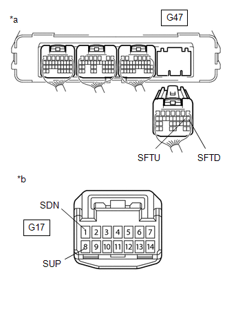
(d) Reconnect the G17 spiral cable sub-assembly connector.
(e) Reconnect the G47 hybrid vehicle control ECU connector.
| NG | |
REPAIR OR REPLACE HARNESS OR CONNECTOR |
|
INSPECT SPIRAL CABLE SUB-ASSEMBLY
(a) Inspect the spiral cable sub-assembly.
Click here
| NG | |
REPLACE SPIRAL CABLE SUB-ASSEMBLY |
|
INSPECT SHIFT PADDLE SWITCH LH (NO. 1 TRANSMISSION SHIFT SWITCH ASSEMBLY)
(a) Inspect the shift paddle switch LH (NO. 1 transmission shift switch assembly).
Click here
| NG | |
REPLACE SHIFT PADDLE SWITCH LH (NO. 1 TRANSMISSION SHIFT SWITCH ASSEMBLY) |
|
INSPECT SHIFT PADDLE SWITCH RH (NO. 2 TRANSMISSION SHIFT SWITCH ASSEMBLY)
(a) Inspect the shift paddle switch RH (NO. 2 transmission shift switch assembly).
Click here
| NG | |
REPLACE SHIFT PADDLE SWITCH RH (NO. 2 TRANSMISSION SHIFT SWITCH ASSEMBLY) |
|
INSPECT NO. 1 SWITCH WIRE
(a) Disconnect the z2 No. 1 switch wire connector.
(b) Measure the resistance according to the value(s) in the table below. Standard Resistance:
|
|
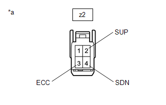
(c) Reconnect the z2 No. 1 switch wire connector.
| OK | |
CHECK FOR INTERMITTENT PROBLEMS |
| NG | |
REPLACE NO. 1 SWITCH WIRE |
Shut Down Signal Circuit
DESCRIPTION
The cause of the malfunction may be a shutdown signal.
Check whether there is a shutdown signal +B short circuit.
Related Parts CheckArea | Inspection |
|---|---|
HSDN terminal |
Check that the HSDN terminal voltage decreases to check for an open or short circuit while READY off (IG ON). |
Hybrid vehicle control ECU, inverter, wire harness |
Check for open or short circuit in hybrid vehicle control ECU, inverter and wire harness. |
SYSTEM DESCRIPTION
Power supply to the motor is cut off due to a shutdown signal sent from the hybrid vehicle control ECU to the motor generator control ECU (MG ECU).
WIRING DIAGRAM
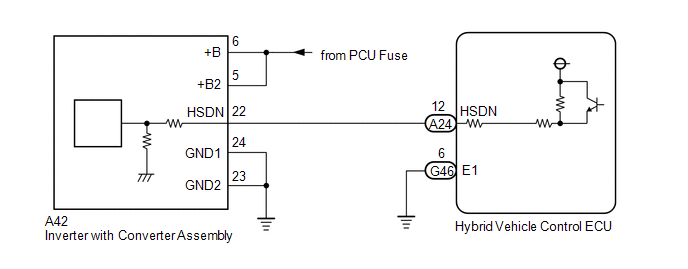
This diagnostic procedure is referenced to in the diagnostic procedure of several DTCs.
If the result of this diagnostic procedure is normal, proceed as directed in the procedure for the DTC.
CAUTION:
- Before the following operations are conducted, take precautions to prevent electric shock by turning the power switch off, wearing insulated gloves, and removing the service plug grip from HV battery.
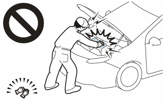
- Inspecting the high-voltage system
- Disconnecting the low voltage connector of the inverter with converter assembly
- Disconnecting the low voltage connector of the HV battery
- To prevent electric shock, make sure to remove the service plug grip to cut off the high voltage circuit before servicing the vehicle.
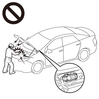
- After removing the service plug grip from the HV battery, put it in your pocket to prevent other technicians from accidentally reconnecting it while you are working on the high-voltage system.
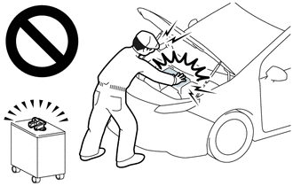
- After removing the service plug grip, wait for at least 10 minutes before touching any of the high-voltage connectors or terminals. After waiting for 10 minutes, check the voltage at the terminals in the inspection point in the inverter with converter assembly. The voltage should be 0 V before beginning work.
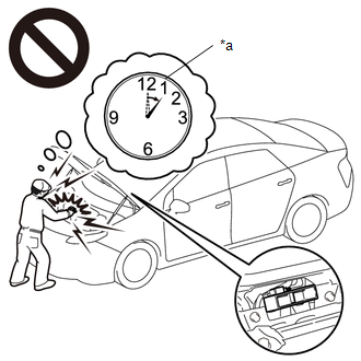
*a
Without waiting for 10 minutes
Click here

HINT:
Waiting for at least 10 minutes is required to discharge the high-voltage capacitor inside the inverter with converter assembly.
NOTICE:
After turning the power switch off, waiting time may be required before disconnecting the cable from the negative (-) auxiliary battery terminal. Therefore, make sure to read the disconnecting the cable from the negative (-) auxiliary battery terminal notices before proceeding with work.
Click here
PROCEDURE
CHECK HYBRID VEHICLE CONTROL ECU
(a) Turn the power switch on (IG).
(b) Measure the voltage according to the value(s) in the table below. Standard Voltage:
|
|
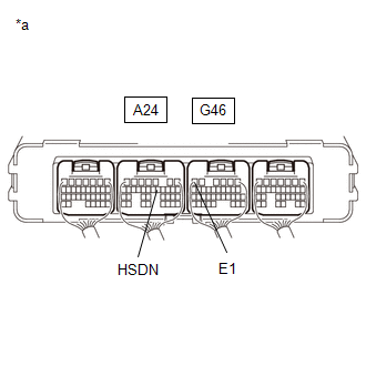
(c) Turn the power switch off.
| OK |  |
SHUTDOWN SIGNAL CIRCUIT NORMAL (PERFORM NEXT STEP FOR REFERENCED DTC) |
|

CHECK HARNESS AND CONNECTOR (HYBRID VEHICLE CONTROL ECU - INVERTER WITH CONVERTER ASSEMBLY)
CAUTION:
Be sure to wear insulated gloves.
(a) Check that the service plug grip is not installed.
NOTICE:
After removing the service plug grip, do not turn the power switch on (READY), unless instructed by the repair manual because this may cause a malfunction.
(b) Disconnect the A42 inverter with converter assembly connector.
(c) Disconnect the A24 hybrid vehicle control ECU connector.
(d) Connect the cable to the negative (-) auxiliary battery terminal.
(e) Turn the power switch on (IG).
(f) Measure the voltage according to the value(s) in the table below. Standard Voltage:
NOTICE: Turning the power switch on (IG) with the hybrid vehicle control ECU and inverter with converter assembly connector disconnected causes other DTCs to be stored. Clear the DTCs after performing this inspection. |
|
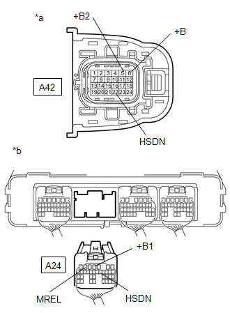
(g) Turn the power switch off.
(h) Disconnect the cable from the negative (-) auxiliary battery terminal, and wait for 2 minutes or more.
(i) Measure the resistance according to the value(s) in the table below.
Standard Resistance:
Tester Connection | Condition | Specified Condition |
|---|---|---|
A42-22 (HSDN) - A42-6 (+B) |
Power switch off |
10 kΩ or higher |
A42-22 (HSDN) - A42-5 (+B2) |
Power switch off |
10 kΩ or higher |
A24-12 (HSDN) - A24-4 (+B1) |
Power switch off |
10 kΩ or higher |
A24-12 (HSDN) - A24-6 (MREL) |
Power switch off |
10 kΩ or higher |
(j) Reconnect the A24 hybrid vehicle control ECU connector.
(k) Reconnect the A42 inverter with converter assembly connector.
| NG | |
REPAIR OR REPLACE HARNESS OR CONNECTOR |
|
CHECK INVERTER WITH CONVERTER ASSEMBLY
CAUTION:
Be sure to wear insulated gloves.
(a) Check that the service plug grip is not installed.
NOTICE:
After removing the service plug grip, do not turn the power switch on (READY), unless instructed by the repair manual because this may cause a malfunction.
(b) Disconnect the A42 inverter with converter assembly connector.
(c) Measure the resistance according to the value(s) in the table below. Standard Resistance:
|
|
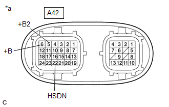
(d) Reconnect the A42 inverter with converter assembly connector.
| OK | |
REPLACE HYBRID VEHICLE CONTROL ECU |
| NG | |
REPLACE INVERTER WITH CONVERTER ASSEMBLY |