Fuel Pump(for High Pressure)
Components
COMPONENTS
ILLUSTRATION
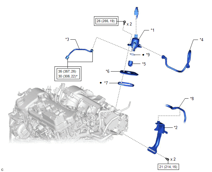
*1 |
FUEL PUMP ASSEMBLY |
*2 |
FUEL PUMP PROTECTOR |
*3 |
NO. 1 FUEL PIPE SUB-ASSEMBLY |
*4 |
NO. 2 FUEL TUBE SUB-ASSEMBLY |
*5 |
FUEL PUMP LIFTER ASSEMBLY |
*6 |
FUEL PUMP LIFTER GUIDE |
*7 |
FUEL PUMP SPACER GASKET |
*8 |
FUEL TUBE SUB-ASSEMBLY |
*9 |
O-RING |
- |
- |
 |
Tightening torque for "Major areas involving basic vehicle performance such as moving/turning/stopping": N*m (kgf*cm, ft.*lbf) |
 |
N*m (kgf*cm, ft.*lbf): Specified torque |
* |
For use with a union nut wrench |
● |
Non-reusable part |
Inspection
INSPECTION
PROCEDURE
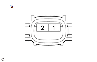
1. INSPECT FUEL PUMP ASSEMBLY
(a) Measure the resistance according to the value(s) in the table below. Standard Resistance:
If the result is not as specified, replace the fuel pump assembly. |
|
Installation
INSTALLATION
PROCEDURE
1. TEMPORARILY INSTALL FUEL PUMP ASSEMBLY
(a) Turn the crankshaft pulley until the flat of the camshaft faces the fuel pump lifter assembly. HINT: This prevents the camshaft nose from pushing up the fuel pump lifter assembly when installing the fuel pump assembly. |
|
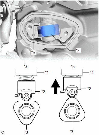
(b) Fill the fuel pump lifter housing oil collection areas with 30 cc (1.8 cu. in.) of engine oil from the fuel pump assembly hole of the cylinder head cover sub-assembly.
(c) Apply engine oil to the pump drive cam and fuel pump lifter assembly. |
|
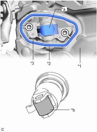
(d) Install a new fuel pump spacer gasket to the cylinder head cover sub-assembly.
(e) Apply engine oil to the inside of the fuel pump lifter housing and the outside of the fuel pump lifter assembly. |
|
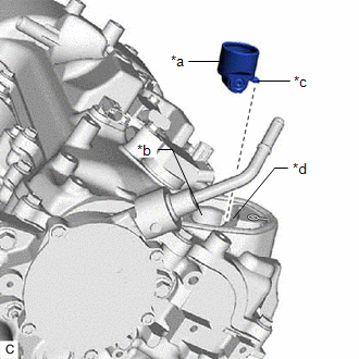
(f) Set the fuel pump lifter assembly on the fuel pump lifter housing as shown in the illustration.
HINT:
Align the stopper key of the fuel pump lifter assembly with the key groove of the fuel pump lifter housing.
(g) Apply engine oil to a new O-ring and install it to the fuel pump assembly.
NOTICE:
Do not damage the O-ring.
(h) Set the fuel pump lifter guide and fuel pump assembly on the cylinder head cover sub-assembly as shown in the illustration. |
|
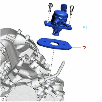
(i) Temporarily install the fuel pump assembly with the 2 bolts, leaving some allowance for left and right movement.
2. TEMPORARILY INSTALL NO. 1 FUEL PIPE SUB-ASSEMBLY
NOTICE:
Do not damage the seals of the union nuts of the No. 1 fuel pipe sub-assembly.
(a) Temporarily install the No. 1 fuel pipe sub-assembly to the fuel delivery pipe RH and tighten the union nut by hand.
(b) Temporarily install the No. 1 fuel pipe sub-assembly to the fuel pump assembly and tighten the union nut by hand.
3. INSTALL FUEL PUMP ASSEMBLY
HINT:
Perform "Inspection After Repair" after replacing the fuel pump assembly.
Click here 
(a) Tighten the 2 bolts.
Torque:
26 N·m {265 kgf·cm, 19 ft·lbf}
(b) Connect the fuel pump assembly connector.
4. INSTALL NO. 1 FUEL PIPE SUB-ASSEMBLY
(a) Using a 17 mm union nut wrench, tighten the union nut on the fuel pump assembly side of the No. 1 fuel pipe sub-assembly. Torque: Specified tightening torque : 35 N·m {357 kgf·cm, 26 ft·lbf} NOTICE: Do not adjust the torque in the loosening direction. HINT:
|
|
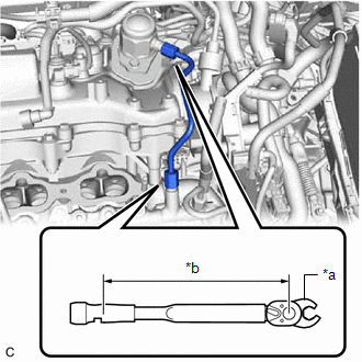
(b) Using a 17 mm union nut wrench, tighten the union nut on the fuel delivery pipe RH side of the No. 1 fuel pipe sub-assembly.
Torque:
Specified tightening torque :
35 N·m {357 kgf·cm, 26 ft·lbf}
NOTICE:
Do not adjust the torque in the loosening direction.
HINT:
- Calculate the torque wrench reading when changing the fulcrum length of the torque wrench.
Click here
- When using a 17 mm union nut wrench (fulcrum length of 30 mm (1.18 in.)) + torque wrench (fulcrum length of 180 mm (7.09 in.)): 30 N*m (306 kgf*cm, 22 ft.*lbf)
5. CONNECT NO. 2 FUEL TUBE SUB-ASSEMBLY
(a) Connect the No. 2 fuel tube sub-assembly to the fuel pump assembly.
Click here
6. INSTALL FUEL PUMP PROTECTOR
(a) Install the fuel pump protector to the cylinder head sub-assembly with the 2 bolts.
Torque:
21 N·m {214 kgf·cm, 15 ft·lbf}
(b) Engage the clamp to connect the fuel tube sub-assembly to the fuel pump protector.
7. INSTALL INTAKE MANIFOLD
Click here
8. CONNECT CABLE TO NEGATIVE BATTERY TERMINAL
Click here
9. INSPECT FOR FUEL LEAK
Click here
10. PERFORM INITIALIZATION
(a) Perform "Inspection After Repair" after replacing the fuel pump assembly.
Click here
On-vehicle Inspection
ON-VEHICLE INSPECTION
PROCEDURE
1. FUEL PUMP ASSEMBLY OPERATION
(a) Check fuel pressure.
(1) Connect the Techstream to the DLC3.
(2) Start the engine.
(3) Turn the Techstream on.
(4) Enter the following menus: Powertrain / Engine / Active Test / Control the Target Fuel Pressure Offset.
Powertrain > Engine > Active TestControl the Target Fuel Pressure Offset
Fuel Pressure (High)
(5) Select the Data List item: Fuel Pressure (High)
(6) Check that the fuel pressure fluctuates when the target fuel pressure changes.
HINT:
The target fuel pressure operation decreases the target fuel pressure by 12.5% or increases the target fuel pressure by 24.8%.
If the result is not as specified, replace the fuel pump assembly or fuel pressure sensor (fuel delivery pipe with sensor assembly LH).
(b) Check operating sound.
(1) Remove the cowl top ventilator louver sub-assembly.
Click here 
(2) Remove the front center upper suspension brace sub-assembly.
Click here
(3) Start the engine.
(4) Using a sound scope, check the operating sound of the fuel pump assembly.
If no sound can be heard, check the fuel pump assembly, wire harness and ECM.
(5) Stop the engine.
(6) Install the front center upper suspension brace sub-assembly.
Click here
(7) Install the cowl top ventilator louver sub-assembly.
Click here
Removal
REMOVAL
The necessary procedures (adjustment, calibration, initialization or registration) that must be performed after parts are removed and installed, or replaced during fuel pump assembly removal/installation are shown below.
Necessary Procedures After Parts Removed/Installed/ReplacedReplaced Part or Performed Procedure | Necessary Procedure | Effect/Inoperative Function when Necessary Procedure not Performed | Link |
|---|---|---|---|
| *: When performing learning using the Techstream. Click here |
|||
Battery terminal is disconnected/reconnected |
Perform steering sensor zero point calibration |
Lane Departure Alert System (w/ Steering Control) |
 |
Pre-collision System |
|||
Intelligent Clearance Sonar System* |
|||
Lighting System (for Gasoline Model with Cornering Light) |
|||
Memorize steering angle neutral point |
Parking Assist Monitor System |
|
|
Panoramic View Monitor System |
|
||
|
Inspection after repair |
|
|
CAUTION:
- Never perform work on fuel system components near any possible ignition sources.
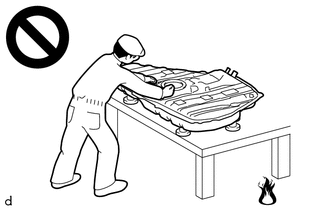
- Vaporized fuel could ignite, resulting in a serious accident.
- Do not perform work on fuel system components without first disconnecting the cable from the negative (-) battery terminal.
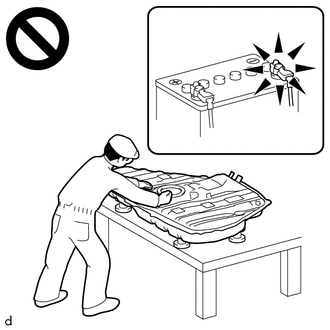
- Sparks could cause vaporized fuel to ignite, resulting in a serious accident.
- To prevent serious injury due to fuel spray from the high-pressure fuel lines, always discharge fuel system pressure before removing any fuel system components.
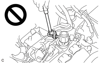
PROCEDURE
1. PRECAUTION
NOTICE:
After turning the engine switch off, waiting time may be required before disconnecting the cable from the negative (-) battery terminal. Therefore, make sure to read the disconnecting the cable from the negative (-) battery terminal notices before proceeding with work.
Click here
2. DISCHARGE FUEL SYSTEM PRESSURE
Click here
3. DISCONNECT CABLE FROM NEGATIVE BATTERY TERMINAL
Click here
4. REMOVE INTAKE MANIFOLD
Click here
5. REMOVE FUEL PUMP PROTECTOR
(a) Disengage the clamp to disconnect the fuel tube sub-assembly from the fuel pump protector. |
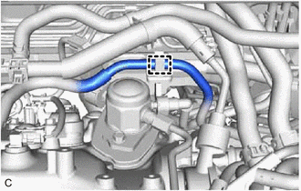 |
(b) Remove the 2 bolts and fuel pump protector from the cylinder head sub-assembly. |
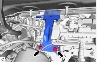 |
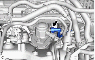
6. DISCONNECT NO. 2 FUEL TUBE SUB-ASSEMBLY
(a) Disconnect the No. 2 fuel tube sub-assembly from the fuel pump assembly. Click here |
 |
7. REMOVE NO. 1 FUEL PIPE SUB-ASSEMBLY
CAUTION:
To prevent serious injury due to fuel spray from the high-pressure fuel lines, always discharge fuel system pressure before removing any fuel system components.
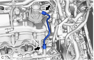
(a) Using a 17 mm union nut wrench, loosen the 2 union nuts of the No. 1 fuel pipe sub-assembly. |
 |
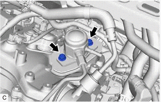
(b) Loosen the 2 bolts of the fuel pump assembly. |
 |
(c) Remove the No. 1 fuel pipe sub-assembly from the fuel delivery pipe RH and fuel pump assembly.
8. REMOVE FUEL PUMP ASSEMBLY
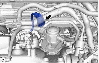
(a) Disconnect the fuel pump assembly connector. |
 |
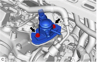
(b) Remove the 2 bolts, fuel pump assembly and fuel pump lifter guide from the cylinder head cover sub-assembly. |
 |
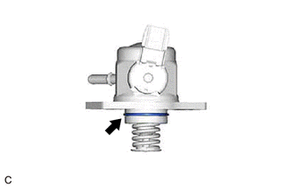
(c) Remove the O-ring from the fuel pump assembly. |
 |
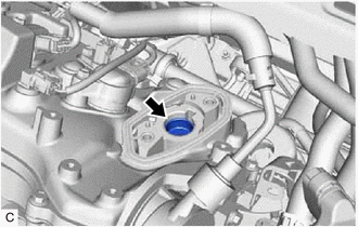
(d) Remove the fuel pump lifter assembly from the fuel pump lifter housing. |
 |
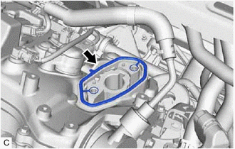
(e) Remove the fuel pump spacer gasket from the cylinder head cover sub-assembly. |
 |