Knock Sensor
Components
COMPONENTS
ILLUSTRATION
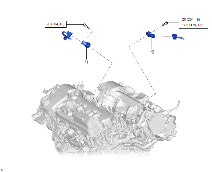
*1 |
KNOCK CONTROL SENSOR (for Bank 1) |
*2 |
KNOCK CONTROL SENSOR (for Bank 2) |
 |
N*m (kgf*cm, ft.*lbf): Specified torque |
* |
For use with a union nut wrench |
Inspection
INSPECTION
PROCEDURE
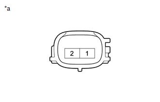
1. INSPECT KNOCK CONTROL SENSOR
(a) Measure the resistance according to the value(s) in the table below. Standard Resistance:
If the result is not as specified, replace the knock control sensor. |
|
Installation
INSTALLATION
PROCEDURE
1. INSTALL KNOCK CONTROL SENSOR
HINT:
Perform "Inspection After Repair" after replacing a knock control sensor.
Click here 
(a) Temporarily install the 2 knock control sensors to the cylinder block sub-assembly with the 2 bolts so that the knock control sensor installation position is as shown in the illustration.
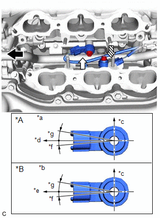
*A |
for Bank 1 |
*B |
for Bank 2 |
*a |
View A |
*b |
View B |
*c |
Top |
*d |
Engine Front |
*e |
Engine Rear |
*f |
5° |
*g |
10° |
 |
Engine Front |
 |
View A |
 |
View B |
NOTICE:
- If a knock control sensor has been struck or dropped, replace it.
- Make sure that the knock control sensor is installed in the correct position.
(b) Tighten the bolt (A). Torque: 20 N·m {204 kgf·cm, 15 ft·lbf} |
|
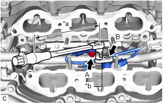
(c) Using a 10 mm union nut wrench, tighten the bolt (B).
Torque:
Specified tightening torque :
20 N·m {204 kgf·cm, 15 ft·lbf}
HINT:
- Calculate the torque wrench reading when changing the fulcrum length of the torque wrench.
Click here
- When using a 10 mm union nut wrench (fulcrum length of 22 mm (0.866 in.)) + torque wrench (fulcrum length of 162 mm (6.38 in.)):
17.6 N*m (179 kgf*cm, 13 ft.*lbf)
(d) Connect the 2 knock control sensor connectors.
2. INSTALL FUEL DELIVERY PIPE
Click here
3. PERFORM INITIALIZATION
(a) Perform "Inspection After Repair" after replacing a knock control sensor.
Click here
Removal
REMOVAL
The necessary procedures (adjustment, calibration, initialization or registration) that must be performed after parts are removed and installed, or replaced during knock control sensor removal/installation are shown below.
Necessary Procedures After Parts Removed/Installed/ReplacedReplaced Part or Performed Procedure | Necessary Procedure | Effect/Inoperative Function when Necessary Procedure not Performed | Link |
|---|---|---|---|
| *: When performing learning using the Techstream. Click here |
|||
Battery terminal is disconnected/reconnected |
Perform steering sensor zero point calibration |
Lane Departure Alert System (w/ Steering Control) |
 |
Pre-collision System |
|||
Intelligent Clearance Sonar System* |
|||
Lighting System (for Gasoline Model with Cornering Light) |
|||
Memorize steering angle neutral point |
Parking Assist Monitor System |
|
|
Panoramic View Monitor System |
|
||
|
Inspection after repair |
|
|
PROCEDURE
1. REMOVE FUEL DELIVERY PIPE
Click here
2. REMOVE KNOCK CONTROL SENSOR
(a) Disconnect the 2 knock control sensor connectors. |
|
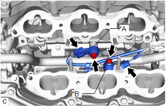
(b) Remove the 2 bolts and 2 knock control sensors from the cylinder block sub-assembly.
NOTICE:
If a knock control sensor has been struck or dropped, replace it.