Dtc Check / Clear. Freeze Frame Data. How To Proceed With Troubleshooting
Dtc Check / Clear
DTC CHECK / CLEAR
CHECK FOR DTC
(a) Connect the Techstream to the DLC3.
(b) Turn the power switch on (IG).
(c) Turn the Techstream on.
(d) Enter the following menus: Powertrain / Motor Generator / Trouble Codes.
Powertrain > Motor Generator > Trouble Codes(e) Check the DTCs and freeze frame data, and then write them down.
(f) Check the details of the DTCs.
Display Item | Description |
|---|---|
Test Failed |
Shows the malfunction judgment results during the current trip. |
Pending |
Shows the malfunction judgment results up to now (Indicates the possibility of a malfunction when no DTC is confirmed.) |
Confirmed |
Shows the DTCs confirmed up to now (The number of current trips differs for each DTC.) |
- A pending DTC is a DTC that is stored in the motor generator control ECU during the 1st trip when 2 trip detection logic is used.
- Freeze frame data is stored for each of the latest result DTCs, pending DTCs and confirmed DTCs.
CHECK FREEZE FRAME DATA
(a) If a DTC is present, select it in order to display its freeze frame data.
(b) Read the freeze frame data recorded when the DTC was stored.
CHECK TIME STAMP
HINT:
By checking Time Stamp, the time and order in which DTCs were stored in an ECU can be checked.
(a) Connect the Techstream to the DLC3.
(b) Turn the power switch on (IG).
(c) Enter the following menus: Health Check.
(d) Perform the following steps when the data setting screen is displayed.
(e) Select the systems for which to perform Health Check and check for time stamp data.
Selectable items:- Powertrain
- Chassis
- Body
- Store All Data
(f) Select "Yes" when "Do you want to store time stamp data?" is displayed.
HINT:
If "Yes" is not selected, time stamp data will not be stored.
(g) After Health Check has completed, select "Time Stamp Data" to display the Time Stamp screen.
(h) Select the desired system from the drop-down list on the bottom of the Time Stamp screen.
(i) Check the order and time which DTCs were stored for the selected system.
CHECK FOR DTC (SYSTEMS EXCEPT MOTOR GENERATOR CONTROL ECU)
HINT:
The motor generator control ECU maintains communication with other ECUs, such as the hybrid vehicle control ECU, ECM and skid control ECU assembly. Therefore, if the motor generator control ECU outputs a DTC, it is necessary to check for and make a note of any DTCs stored for other systems.
(a) If DTCs are present, check the relevant systems.
HINT:
If DTCs for the CAN communication system are present in addition to other DTCs, first troubleshoot and repair in the CAN communication system malfunctions.
CLEAR DTC
(a) Connect the Techstream to the DLC3.
(b) Turn the power switch on (IG).
(c) Turn the Techstream on.
(d) Enter the following menus: Powertrain / Motor Generator / Trouble Codes.
(e) Clear the DTCs and freeze frame data.
Powertrain > Motor Generator > Clear DTCsNOTICE:
Clearing the DTCs will also clear the freeze frame data, diagnosis related information.
CLEAR PERMANENT DTC
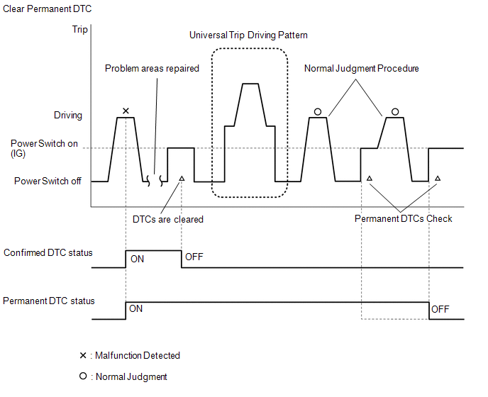
OUTLINE- After clearing current DTCs using the Techstream (or by disconnecting the cable from the negative (-) auxiliary battery terminal), permanent DTCs can be cleared when the universal trip is performed and then the system is determined to be normal for the relevant DTCs. The driving pattern to obtain a normal judgment is described under the "Confirmation Driving Pattern" for the respective DTC.
- To clear permanent DTCs, all of the following conditions must be are met:
- There is a history that universal trip driving was performed.
- The vehicle has been judged as normal for 2 trips. (Normal judgment does not have to be performed in 2 consecutive trip, but normal judgment should occur in the latest trip.)
- No malfunctions are detected.
(a) Connect the Techstream to the DLC3.
(b) Turn the power switch on (IG).
(c) Turn the Techstream on.
(d) Enter the following menus: Powertrain / Motor Generator / Trouble Codes.
Powertrain > Motor Generator > Trouble CodesHINT:
If "YES" is displayed for the value of "PERMANENT" at the top right of the Techstream screen, permanent DTCs are stored.
(e) Select the "Generic" tab.
(f) Check if permanent DTCs are stored.
HINT:
If permanent DTCs are not output, it is not necessary to continue this procedure.
(g) Clear the DTCs (even if no DTCs are stored, perform the clear DTC procedure).
Powertrain > Motor Generator > Clear DTCsNOTICE:
Do not clear the DTCs or disconnect the cable from the auxiliary battery terminal after performing this step.
(h) Perform the universal trip.
CAUTION:
When performing the driving pattern, obey all speed limits and traffic laws.
HINT:
The universal trip driving pattern and normal judgment procedure can be performed consecutively in the same driving cycle.
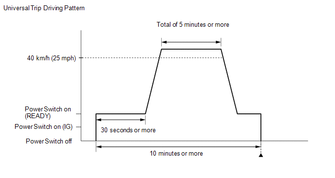
(1) Turn the power switch on (READY) and wait for 30 seconds or more.
(2) Drive the vehicle at 40 km/h or more for a total of 5 minutes or more.
HINT:
It is possible to complete the drive pattern even if the vehicle decelerates to less than 40 km/h during the driving cycle provided that the vehicle is driven at 40 km/h or more for a total of 5 minutes.
(3) Allow 10 minutes or more to elapse from the time the power switch turned on (READY).
(i) Turn the power switch off and wait for 2 minutes or more.
(j) Perform the normal judgment procedure in the respective confirmation driving pattern of each output DTC.
HINT:
Do not turn the power switch off by mistake during this step.
(k) With power switch on (READY) and wait for 5 seconds or more.
(l) Turn the power switch off and wait for 2 minutes or more.
(m) Turn the power switch on (IG).
(n) Enter the following menus: Powertrain / Motor Generator / Trouble Codes.
Powertrain > Motor Generator > Trouble Codes(o) Check that the permanent DTCs have been cleared.
HINT:
If permanent DTCs are not output, it is not necessary to continue this procedure.
(p) Perform the normal judgment procedure in the respective confirmation driving pattern of each output DTC.
HINT:
Do not turn the power switch off by mistake during this step.
(q) With power switch on (READY) and wait for 5 seconds or more.
(r) Turn the power switch off and wait for 2 minutes or more.
(s) Turn the power switch on (IG).
(t) Enter the following menus: Powertrain / Motor Generator / Trouble Codes.
Powertrain > Motor Generator > Trouble Codes(u) Check that the permanent DTCs have been cleared.
HINT:
Permanent DTCs will be cleared if a normal judgment is obtained during 3 consecutive driving cycles with the MIL illuminated.
Freeze Frame Data
FREEZE FRAME DATA
FREEZE FRAME DATA
HINT:
The motor generator control ECU records vehicle and driving condition information as freeze frame data the moment a DTC is stored. It can be used for estimating or duplicating the vehicle conditions that were present when the malfunction occurred.
(a) Connect the Techstream to the DLC3.
(b) Turn the power switch on (IG).
(c) Turn the Techstream on.
(d) Enter the following menus: Powertrain / Hybrid Control / Trouble Codes.
(e) Select a DTC in order to display its freeze frame data.
(f) Check the freeze frame data recorded with the DTC.
Powertrain > Motor GeneratorTester Display | Measurement Item | Range | Diagnostic Note |
|---|---|---|---|
Calculate Load |
Calculate load (value increases in proportion to increase in load) |
Min.: 0.0%, Max.: 100.0% |
- |
Coolant Temperature |
Engine coolant temperature |
Min.: -40°C (-40°F), Max.: 215 °C |
Cold or warmed-up engine |
Engine Speed |
Engine speed |
Min.: 0 rpm, Max.: 16383 rpm |
- |
Vehicle Speed |
Vehicle speed |
Min.: 0 km/h, Max.: 255 km/h |
Stopped, or driving (at low, medium, or high speeds) |
Intake Air Temperature |
Intake air temperature |
Min.: -40°C (-40°F), Max.: 140 °C |
- |
Throttle Position Sensor No.1 Voltage % |
Throttle position sensor |
Min.: 0.0%, Max.: 100.0% |
- |
Engine Run Time |
Elapsed time after starting engine |
Min.: 0 sec, Max.: 65535 sec |
After the power switch is turned on (READY), elapsed time from initial engine start until the power switch is turned off. |
MIL ON Run Distance |
Drive distance from MIL on |
Min.: 0 km (0 mile), Max.: 65535 km (40723 mile) |
- |
Warmup Cycle Cleared DTC |
Warmup cycles after DTCs cleared |
Min.: 0, Max.: 255 |
- |
Distance from DTC Cleared |
Distance driven after DTCs cleared |
Min.: 0 km (0 mile), Max.: 65535 km (40723 mile) |
- |
Battery Voltage |
Auxiliary battery voltage |
Min.: 0.00 V, Max.: 16.00 V |
Auxiliary battery and DC/DC converter condition |
Ambient Temperature |
Ambient air temperature |
Min.: -40°C (-40°F), Max.: 215 °C |
- |
Running Time from MIL ON |
Running time from MIL on |
Min.: 0 min, Max.: 65535 min |
- |
Time after DTC Cleared |
Time after DTCs cleared |
Min.: 0 min, Max.: 65535 min |
- |
Shift SW Status (N,P Range) |
Shift lever position sensor |
ON or OFF |
- |
Hybrid/EV Battery System Voltage |
HV battery voltage |
Min.: 0.00 V, Max.: 1023.98 V |
- |
Hybrid/EV Battery System Current |
HV battery current |
Min.: -3276.8 A, Max.: 3276.7 A |
HV battery charge/discharge status
|
Boosting Converter Temperature(Upper) |
Boost converter temperature (Upper) |
Min.: 8 °C, Max.: 150 °C |
- |
Boosting Converter Temperature 1(Lower) |
Boost converter temperature 1 (Lower) |
Min.: 8 °C, Max.: 150 °C |
- |
Boosting Converter Temperature 2(Lower) |
Boost converter temperature 2 (Lower) |
Min.: 8 °C, Max.: 150 °C |
- |
Motor Inverter Temperature |
Motor inverter temperature |
Min.: 8 °C, Max.: 150 °C |
- |
Motor U Current(Lower Resolution) |
Motor U current (Lower resolution) |
Min.: -3276.8 A, Max.: 3276.7 A |
- |
Motor V Current(Lower Resolution) |
Motor V current (Lower resolution) |
Min.: -3276.8 A, Max.: 3276.7 A |
- |
Motor W Current(Lower Resolution) |
Motor W current (Lower resolution) |
Min.: -3276.8 A, Max.: 3276.7 A |
- |
Generator U Current(Lower Resolution) |
Generator U current (Lower resolution) |
Min.: -3276.8 A, Max.: 3276.7 A |
- |
Generator V Current(Lower Resolution) |
Generator V current (Lower resolution) |
Min.: -3276.8 A, Max.: 3276.7 A |
- |
Generator W Current(Lower Resolution) |
Generator W current (Lower resolution) |
Min.: -3276.8 A, Max.: 3276.7 A |
- |
Motor ECU Power Supply (For 31V) |
Motor generator control ECU power supply (for 31V) |
Min.: 0.00 V, Max.: 4.98 V |
- |
Motor ECU Power Supply (For AD0) |
Motor generator control ECU power supply (for AD0) |
Min.: 0.00 V, Max.: 4.98 V |
- |
Motor ECU Power Supply (For 2.5V) |
Motor generator control ECU power supply (for 2.5V) |
Min.: 0.00 V, Max.: 4.98 V |
- |
Motor ECU Power Supply (For 2.5V Sub) |
Motor generator control ECU power supply (for 2.5V sub) |
Min.: 0.00 V, Max.: 4.98 V |
- |
DC/DC Converter Operation State |
DC/DC converter operation state |
Min.: 0.00 V, Max.: 4.98 V |
- |
DC/DC Converter Output Signal |
DC/DC converter output signal |
Min.: 0.00 V, Max.: 4.98 V |
- |
DC/DC Converter Output Signal Duty |
DC/DC converter output signal duty |
Min.: 0.0 %, Max.: 100.0 % |
- |
Motor Revolution |
Motor (MG2) speed (detected by resolver sensor) |
Min.: -32768 rpm, Max.: 32767 rpm |
Motor (MG2) speed
|
Motor Torque |
Motor (MG2) torque value |
Min.: -4096.0 N·m, Max.: 4096 N·m |
When motor (MG2) rotates in "+" direction:
When motor (MG2) rotates in "-" direction:
|
Motor Control Mode |
Motor control mode |
Min.: 0, Max.: 65535 |
- |
Motor Carrier Frequency |
Motor carrier frequency |
0.75 kHz, 1.25 kHz, 2.5 kHz, 3.75 kHz, 5 kHz, 10 kHz |
- |
Motor Inverter Shut Down Signal |
Motor inverter shutdown signal |
Min.: 0, Max.: 255 |
- |
Generator Revolution |
Generator (MG1) speed (detected by resolver sensor) |
Min.: -32768 rpm, Max.: 32767 rpm |
Generator (MG1) speed
|
Generator Torque |
Generator (MG1) torque value |
Min.: -4096.0 N·m, Max.: 4096 N·m |
When generator (MG1) rotates in "+" direction:
When generator (MG1) rotates in "-" direction:
|
Generator Control Mode |
Generator control mode |
Min.: 0, Max.: 65535 |
- |
Generator Carrier Frequency |
Generator carrier frequency |
0.75 kHz, 1.25 kHz, 2.5 kHz, 3.75 kHz, 5 kHz, 10 kHz |
- |
Generator Inverter Shut Down Signal |
Generator (MG1) inverter shutdown signal |
Min.: 0, Max.: 255 |
- |
Inverter Coolant Temperature |
Coolant (for inverter) temperature |
Min.: -40°C (-40°F), Max.: 215 °C |
- |
Inverter Input Current |
Inverter input current |
Min.: -3276.8 A, Max.: 3276.7 A |
- |
Inverter Water Pump Duty |
Inverter water pump motor driver request duty |
Min.: 0 %, Max.: 100 % |
- |
Inverter Water Pump Revolution |
Inverter water pump assembly speed |
Min.: 0 rpm, Max.: 15000 rpm |
- |
Collinear Graphic Engine Revolution |
Col-linear graphic engine revolution |
Min.: 0 rpm, Max.: 65535 rpm |
- |
Motor Resolver After Offset |
Motor resolver offset value |
Min.: 0.000 deg, Max.: 358.593 deg |
- |
Motor Resolver Offset Value |
Motor Resolver Offset Value |
Min.: -250.000 deg, Max.: 249.992 deg |
- |
Generator Resolver After Offset |
Generator resolver offset value |
Min.: 0.000 deg, Max.: 358.593 deg |
- |
Generator Resolver Offset Value |
Generator resolver offset value |
Min.: -250.000 deg, Max.: 249.992 deg |
- |
VL Voltage |
High voltage before it is boosted |
Min.: 0.0 V, Max.: 6553.5 V |
- |
VH Voltage |
High voltage after it is boosted |
Min.: 0.0 V, Max.: 6553.5 V |
- |
Boosting Converter PWM Duty |
Boost converter PWM duty |
Min.: 0 %, Max.: 100 % |
- |
Boosting Converter Control Mode |
Boost converter control mode |
Min.: 0, Max.: 255 |
- |
Boosting Converter Carrier Frequency |
Boost converter signal carrier frequency |
9.55 kHz, 9.13 kHz, 8.71 kHz, 8.29 kHz, 7.87 kHz, 7.45 kHz, 4.8 kHz |
- |
Boosting Converter Shut Down Signal |
Boost converter shutdown signal |
Min.: 0, Max.: 255 |
- |
Generate Request Torque |
Generator (MG1) torque request value |
Min.: -4096.0 N·m, Max.: 4096 N·m |
- |
Shift Position |
Shift position |
P/R/N/D |
- |
Motor Temperature |
Motor (MG2) temperature |
Min.: -40°C (-40°F), Max.: 215 °C |
- |
Generator Temperature |
Generator (MG1) temperature |
Min.: -40°C (-40°F), Max.: 215 °C |
- |
Short Wave Highest Value |
Waveform voltage in abnormal insulation detection circuit in battery voltage sensor |
Min.: 0.00 V, Max.: 4.98 V |
- |
Fail Safe Mode |
Fail safe mode |
Min.: -128, Max.: 127 |
- |
Accelerator Position |
Accelerator pedal opening angle |
Min.: 0 %, Max.: 100.0 % |
- |
WIN Control Limit Power |
Charge control wattage sent from battery voltage sensor to hybrid vehicle control ECU |
Min.: -327.68 kW, Max.: 327.67 kW |
- |
WOUT Control Limit Power |
Discharge control wattage sent from battery voltage sensor to hybrid vehicle control ECU |
Min.: -327.68 kW, Max.: 327.67 kW |
- |
Engine Control Mode |
Engine control mode |
Stop, Stop Process, Startup Process, Running |
- |
Emergency Shutdown Signal |
Inverter emergency shutdown |
ON or OFF |
- |
Ready ON Status |
State of system (READY) |
ON or OFF |
- |
SMR Status |
SMR status |
ON or OFF |
- |
Generator Resolver Offset Complete Status |
Generator resolver learning complete status |
ON or OFF |
- |
Generator Inverter High Current(GFINV) |
Generator (MG1) inverter high current |
ON or OFF |
- |
Generator Inverter Shut Down Status |
Generator (MG1) inverter shutdown status |
ON or OFF |
- |
Motor Resolver Offset Complete Status |
Motor resolver learning complete status |
ON or OFF |
- |
PTC Heater Activate Permission Status/Prohibition Signal(IDH) |
PTC heater |
ON or OFF |
- |
DC/DC Converter Terminate Signal |
DC/DC converter stop request signal |
ON or OFF |
- |
Motor Inverter High Current(MFINV) |
Motor inverter high current |
ON or OFF |
- |
Motor Inverter Shut Down Status |
Motor inverter shutdown |
ON or OFF |
- |
Inverter Input High Voltage(OVH) |
Inverter input high voltage |
ON or OFF |
- |
Boosting Converter Input High Voltage(OVL) |
Boost converter input high voltage |
ON or OFF |
- |
Boosting Converter Input High Current(CFINV) |
Boost converter input high current |
ON or OFF |
- |
Boosting Converter Shut Down Status |
Boost converter shutdown |
ON or OFF |
- |
Total Distance Traveled |
Drive total distance |
Min.: 0 km (0 mile), Max.: 16777215 km (10425361 mile) |
- |
Total Distance Traveled - Unit |
Drive total distance unit |
km or mile |
- |
How To Proceed With Troubleshooting
HINT:
- *: Use the Techstream
- Use the following procedure to troubleshoot the motor generator control system.
PROCEDURE
VEHICLE BROUGHT TO WORKSHOP
|

CUSTOMER PROBLEM ANALYSIS
|
CONNECT TECHSTREAM TO THE DLC3*
HINT:
If the Techstream indicates a communication error, inspect the DLC3.
|
CHECK DTC AND FREEZE FRAME DATA*
Click here 
HINT:
Make sure to save freeze frame data because the data is necessary for performing simulation tests.
|
CLEAR DTC AND FREEZE FRAME DATA*
Click here
|
CONDUCT VISUAL INSPECTION
|
CONFIRM PROBLEM SYMPTOMS
HINT:
If the hybrid vehicle control system does not start, perform steps 9 and 11 first.
| Malfunction occurs. |  |
GO TO STEP 10 |
|
DUPLICATE CONDITIONS THAT PRODUCE SYMPTOMS
|
CHECK FOR DTCS*
Click here
| DTCs are not output. | |
GO TO STEP 16 |
|
REFER TO DTC CHART
|
CONDUCT CIRCUIT INSPECTION
| Malfunction confirmed. | |
GO TO STEP 13 |
|
CHECK FOR INTERMITTENT PROBLEMS
Click here
|
IDENTIFY PROBLEM
|
ADJUST AND/OR REPAIR
|
CONDUCT CONFIRMATION TEST
| NEXT | |
END |
CONDUCT BASIC INSPECTION
| Malfunctioning parts confirmed. | |
GO TO STEP 18 |
|
CHECK ECU POWER SOURCE CIRCUIT
| NEXT | |
GO TO STEP 11 |
CONDUCT PARTS INSPECTION
| NEXT | |
GO TO STEP 13 |