Egr Valve
Components
COMPONENTS
ILLUSTRATION
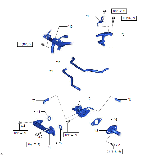
*1 |
NO. 1 EGR PIPE SUB-ASSEMBLY |
*2 |
EGR VALVE ASSEMBLY |
*3 |
EGR VALVE BRACKET |
*4 |
EGR INLET GASKET |
*5 |
EGR VALVE ADAPTER GASKET |
*6 |
EGR VALVE GASKET |
*7 |
NO. 8 WATER BY-PASS HOSE |
*8 |
NO. 4 WATER BY-PASS HOSE |
*9 |
FUEL PIPE SUB-ASSEMBLY |
*10 |
ENGINE WIRE |
*11 |
NO. 1 FUEL VAPOR FEED HOSE |
*12 |
NO. 2 FUEL VAPOR FEED HOSE |
*13 |
EGR COOLER ASSEMBLY |
- |
- |
 |
N*m (kgf*cm, ft.*lbf): Specified torque |
● |
Non-reusable part |
Inspection
INSPECTION
PROCEDURE
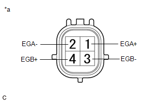
1. INSPECT EGR VALVE ASSEMBLY
(a) Measure the resistance according to the value(s) in the table below. Standard Resistance:
If the result is not as specified, replace the EGR valve assembly. |
|
Installation
INSTALLATION
NOTICE:
This procedure includes the installation of small-head bolts. Refer to Small-Head Bolts of Basic Repair Hint to identify the small-head bolts.
Click here 
PROCEDURE
1. INSTALL EGR VALVE ASSEMBLY
HINT:
Perform "Inspection After Repair" after replacing the EGR valve assembly.
Click here
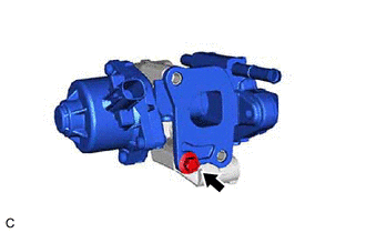
(a) Using an 8 mm socket wrench, install the EGR valve assembly to the EGR valve bracket with the bolt.
Torque:
10 N·m {102 kgf·cm, 7 ft·lbf}
(b) Align and fit the hole of the EGR valve bracket to the pin of the camshaft housing. |
|
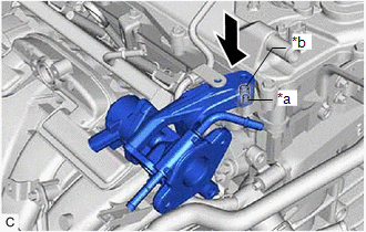
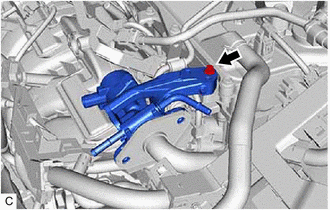
(c) Using the 8 mm socket wrench, install the EGR valve assembly with the EGR valve bracket to the camshaft housing with the bolt.
Torque:
10 N·m {102 kgf·cm, 7 ft·lbf}
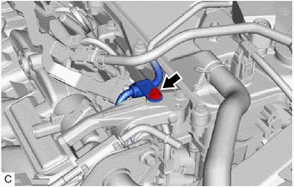
(d) Using the 8 mm socket wrench, connect the fuel pipe sub-assembly to the EGR valve bracket with the bolt.
Torque:
10 N·m {102 kgf·cm, 7 ft·lbf}
(e) Connect the No. 4 water by-pass hose and No. 8 water by-pass hose to the EGR valve assembly and slide the 2 clips to secure them.
2. INSTALL NO. 1 EGR PIPE SUB-ASSEMBLY
(a) Install a new EGR inlet gasket to the intake manifold.
(b) Install a new EGR valve adapter gasket to the No. 1 EGR pipe sub-assembly.
(c) Using an 8 mm socket wrench, install the No. 1 EGR pipe sub-assembly to the intake manifold and EGR valve assembly with the 4 bolts.
Torque:
10 N·m {102 kgf·cm, 7 ft·lbf}
3. CONNECT EGR COOLER ASSEMBLY
(a) Install a new EGR valve gasket to the EGR valve assembly. NOTICE: Make sure that the claws of the EGR valve gasket are toward the EGR valve assembly side. |
|
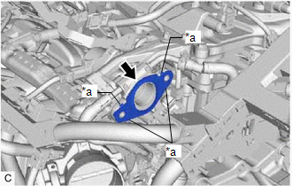
(b) Connect the EGR cooler assembly to the EGR valve assembly with the 2 bolts.
Torque:
21 N·m {214 kgf·cm, 15 ft·lbf}
4. CONNECT ENGINE WIRE
(a) Engage the 2 wire harness clamps to connect the engine wire.
(b) Install the bolt.
Torque:
10 N·m {102 kgf·cm, 7 ft·lbf}
(c) Connect the EGR valve assembly connector.
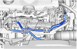
(d) Engage the 3 hose clamps to connect the No. 1 fuel vapor feed hose and No. 2 fuel vapor feed hose. |
|
5. ADD ENGINE COOLANT (for Engine)
Click here
6. INSPECT FOR COOLANT LEAK (for Engine)
Click here
7. INSPECT FOR EXHAUST GAS LEAK
Click here
8. PERFORM INITIALIZATION
(a) Perform "Inspection After Repair" after replacing the EGR valve assembly.
Click here
Removal
REMOVAL
The necessary procedures (adjustment, calibration, initialization or registration) that must be performed after parts are removed and installed, or replaced during EGR valve assembly removal/installation are shown below.
Necessary Procedures After Parts Removed/Installed/ReplacedReplaced Part or Performed Procedure | Necessary Procedures | Effect/Inoperative Function when Necessary Procedure not Performed | Link |
|---|---|---|---|
|
Inspection After Repair |
|
 |
NOTICE:
This procedure includes the removal of small-head bolts. Refer to Small-Head Bolts of Basic Repair Hint to identify the small-head bolts.
Click here
PROCEDURE
1. DRAIN ENGINE COOLANT (for Engine)
Click here
2. DISCONNECT ENGINE WIRE
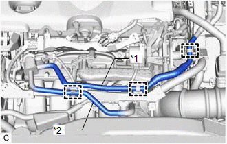
(a) Disengage the 3 hose clamps and disconnect the No. 1 fuel vapor feed hose and No. 2 fuel vapor feed hose. |
|
(b) Disconnect the EGR valve assembly connector. |
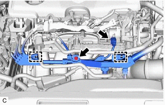 |
(c) Remove the bolt.
(d) Disengage the 2 wire harness clamps and disconnect the engine wire.
3. DISCONNECT EGR COOLER ASSEMBLY
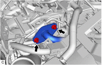
(a) Remove the 2 bolts and disconnect the EGR cooler assembly from the EGR valve assembly. |
 |
(b) Remove the EGR valve gasket from the EGR valve assembly.
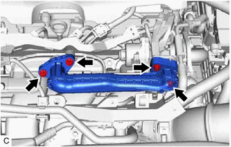
4. REMOVE NO. 1 EGR PIPE SUB-ASSEMBLY
(a) Using an 8 mm socket wrench, remove the 4 bolts and No. 1 EGR pipe sub-assembly from the intake manifold and EGR valve assembly. |
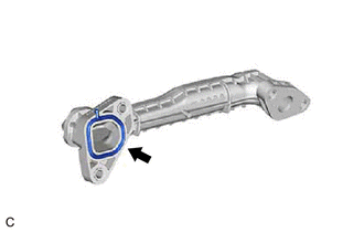
 |
(b) Remove the EGR valve adapter gasket from the No. 1 EGR pipe sub-assembly. |
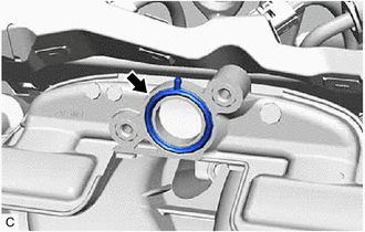
 |
(c) Remove the EGR inlet gasket from the intake manifold. |
 |
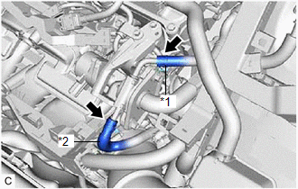
5. REMOVE EGR VALVE ASSEMBLY
(a) Slide the 2 clips and disconnect the No. 4 water by-pass hose and No. 8 water by-pass hose from the EGR valve assembly. |
|
(b) Using an 8 mm socket wrench, remove the bolt and disconnect the fuel pipe sub-assembly from the EGR valve bracket. |
 |
(c) Using the 8 mm socket wrench, remove the bolt. |
 |
(d) Remove the EGR valve assembly with the EGR valve bracket from the camshaft housing vertically. |
|
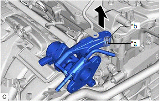
(e) Using the 8 mm socket wrench, remove the bolt and EGR valve assembly from the EGR valve bracket. |
 |