Cylinder Head
Components
COMPONENTS
ILLUSTRATION
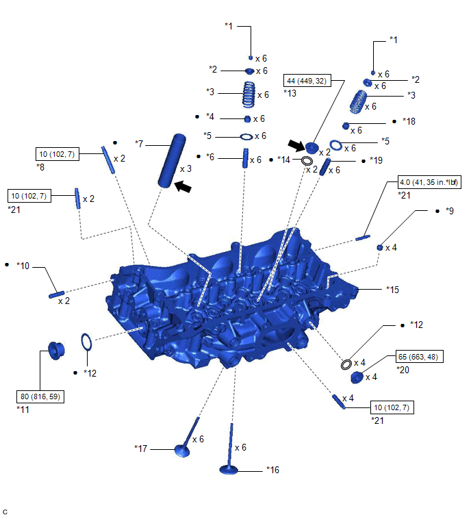
*1 |
VALVE SPRING RETAINER LOCK |
*2 |
VALVE SPRING RETAINER |
*3 |
INNER COMPRESSION SPRING |
*4 |
INTAKE VALVE STEM OIL SEAL |
*5 |
VALVE SPRING SEAT |
*6 |
INTAKE VALVE GUIDE BUSH |
*7 |
SPARK PLUG TUBE |
*8 |
INTAKE MANIFOLD TO CYLINDER HEAD STUD BOLT |
*9 |
RING PIN |
*10 |
STRAIGHT PIN |
*11 |
NO. 2 STRAIGHT SCREW PLUG |
*12 |
CYLINDER HEAD SCREW PLUG GASKET |
*13 |
NO. 1 STRAIGHT SCREW PLUG |
*14 |
WATER HOLE GASKET |
*15 |
CYLINDER HEAD LH |
*16 |
INTAKE VALVE |
*17 |
EXHAUST VALVE |
*18 |
EXHAUST VALVE STEM OIL SEAL |
*19 |
EXHAUST VALVE GUIDE BUSH |
*20 |
NO. 3 STRAIGHT SCREW PLUG |
*21 |
STUD BOLT |
- |
- |
 |
N*m (kgf*cm, ft.*lbf): Specified torque |
● |
Non-reusable part |
 |
Adhesive 1324 |
★ |
Precoated part |
Disassembly
DISASSEMBLY
The necessary procedures (adjustment, calibration, initialization or registration) that must be performed after parts are removed and installed, or replaced during engine unit removal/installation are shown below.
Necessary Procedure After Parts Removed/Installed/ReplacedReplaced Part or Performed Procedure | Necessary Procedure | Effect/Inoperative Function when Necessary Procedure not Performed | Link |
|---|---|---|---|
Battery terminal is disconnected/reconnected |
Perform steering sensor zero point calibration |
Lane departure alert system (w/ Steering Control) |
 |
Pre-collision system |
|||
Intelligent Clearance Sonar System*1 |
|||
Lighting System (for Gasoline Model with Cornering Light) |
|||
Memorize steering angle neutral point |
Parking Assist Monitor System |
|
|
Panoramic View Monitor System |
|
||
Replacement of ECM |
Vehicle Identification Number (VIN) registration |
MIL comes on |
|
ECU communication ID registration (Immobiliser system) |
Engine start function |
|
|
|
Inspection after repair |
|
|
Replacement of automatic transaxle assembly |
|
|
|
Replacement of ECM (If transaxle compensation code read from ECM) |
|
||
Replacement of ECM (If transaxle compensation code not read from ECM) |
|
||
Replacement of automatic transaxle fluid |
ATF thermal degradation estimate reset |
The value of the Data List item "ATF Thermal Degradation Estimate" is not estimated correctly |
|
Replacement of ECM |
Code registration (Smart Key System (for Start Function)) |
|
|
Suspension, tires, etc. |
|
|
|
Rear television camera assembly optical axis adjustment (Back camera position setting) |
Parking Assist Monitor System |
|
|
|
Panoramic View Monitor System |
|
|
Perform headlight ECU sub-assembly LH initialization |
Lighting system (for Gasoline Model with Cornering Light) |
|
|
Front wheel alignment adjustment |
Perform system variant learning and acceleration sensor zero point calibration. |
|
|
- *1: When performing learning using the Techstream.
Click here
- *2: Not necessary when ECM replaced with new one.
PROCEDURE
1. REMOVE INTAKE VALVE
(a) Using SST and wooden blocks, compress the inner compression spring and remove the 6 valve spring retainer locks from the valve spring retainer. SST: 09202-70020 09202-01010 09202-01020 SST: 09202-00021 HINT: Arrange the removed parts in such a way that they can be reinstalled to their original locations. |
|
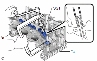
(b) Remove the 6 valve spring retainers, 6 inner compression springs and 6 intake valves from the cylinder head LH.
HINT:
Arrange the removed parts in such a way that they can be reinstalled to their original locations.
2. REMOVE EXHAUST VALVE
(a) Using SST and wooden blocks, compress the inner compression spring and remove the 6 valve spring retainer locks from the valve spring retainer. SST: 09202-70020 09202-01010 09202-01020 SST: 09202-00021 HINT: Arrange the removed parts in such a way that they can be reinstalled to their original locations. |
|
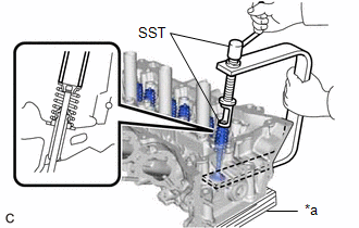
(b) Remove the 6 valve spring retainers, 6 inner compression springs and 6 exhaust valves from the cylinder head LH.
HINT:
Arrange the removed parts in such a way that they can be reinstalled to their original locations.
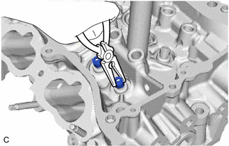
3. REMOVE INTAKE VALVE STEM OIL SEAL
(a) Using needle-nose pliers, remove the 6 intake valve stem oil seals from the intake valve guide bush. |
 |
4. REMOVE EXHAUST VALVE STEM OIL SEAL
HINT:
Use the same procedure as for the intake side.
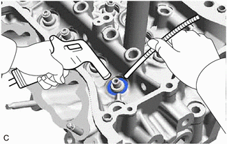
5. REMOVE VALVE SPRING SEAT
(a) Using compressed air and a Magnet Hand, remove the 12 valve spring seats by blowing air onto them from the cylinder head LH. HINT: Arrange the removed parts in such a way that they can be reinstalled to their original locations. |
 |
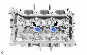
6. REMOVE NO. 1 STRAIGHT SCREW PLUG
NOTICE:
If coolant leaks from a No. 1 straight screw plug or a plug is corroded, replace it.
(a) Using a 10 mm hexagon socket wrench, remove the 2 No. 1 straight screw plugs and 2 water hole gaskets from the cylinder head LH. |
 |
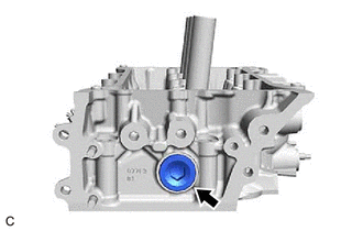
7. REMOVE NO. 2 STRAIGHT SCREW PLUG
NOTICE:
If coolant leaks from a No. 2 straight screw plug or a plug is corroded, replace it.
(a) Using a 14 mm hexagon wrench, remove the No. 2 straight screw plug and cylinder head screw plug gasket from the cylinder head LH. |
 |
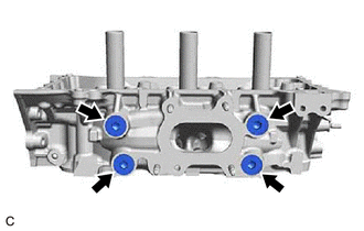
8. REMOVE NO. 3 STRAIGHT SCREW PLUG
NOTICE:
If coolant leaks from a No. 3 straight screw plug or a plug is corroded, replace it.
(a) Using a 10 mm hexagon socket wrench, remove the 4 No. 3 straight screw plugs and 4 cylinder head screw plug gaskets from the cylinder head LH. |
 |
Inspection
INSPECTION
HINT:
- Use the same procedure for bank 1 and bank 2.
- The following procedure is for bank 2.
PROCEDURE
1. INSPECT CYLINDER HEAD LH
(a) Using a precision straightedge and feeler gauge, check the surfaces which contact the cylinder block sub-assembly and manifolds for warpage.
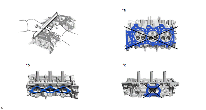
*a |
Bottom Side |
*b |
Intake Manifold Side |
*c |
Exhaust Manifold Side |
- |
- |
Standard Warpage:
Item | Specified Condition |
|---|---|
Bottom Side |
0.05 mm (0.00197 in.) |
Intake Manifold Side |
0.08 mm (0.00315 in.) |
Exhaust Manifold Side |
0.08 mm (0.00315 in.) |
Maximum Warpage:
Item | Specified Condition |
|---|---|
Bottom Side |
0.10 mm (0.00394 in.) |
Intake Manifold Side |
0.10 mm (0.00394 in.) |
Exhaust Manifold Side |
0.10 mm (0.00394 in.) |
HINT:
If the warpage is more than the maximum, replace the cylinder head LH.
2. INSPECT CYLINDER HEAD LH FOR CRACKS
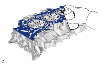
(a) Using a dye penetrant, check the intake ports, exhaust ports and bottom surface of the cylinder head LH for cracks. HINT: If cracks are found, replace the cylinder head LH. |
 |
3. INSPECT INTAKE VALVE
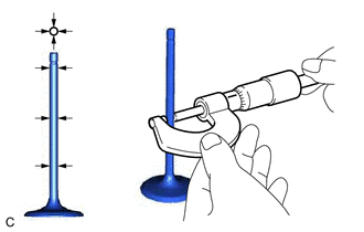
(a) Using a micrometer, measure the diameter of the valve stem. Standard Valve Stem Diameter: 5.470 to 5.485 mm (0.215 to 0.216 in.) HINT: If the valve stem diameter is not as specified, check the intake valve guide bush oil clearance. |
 |
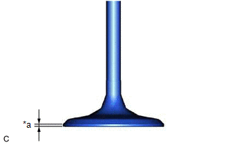
(b) Using a vernier caliper, measure the valve head margin thickness. Standard Margin Thickness: 1.0 mm (0.0394 in.) Minimum Margin Thickness: 0.5 mm (0.0197 in.) HINT: If the margin thickness is less than the minimum, replace the intake valve. |
|
(c) Using a vernier caliper, measure the overall length of the intake valve. Standard Overall Length: 105.85 mm (4.17 in.) Minimum Overall Length: 105.35 mm (4.15 in.) HINT: If the overall length is less than the minimum, replace the intake valve. |
|
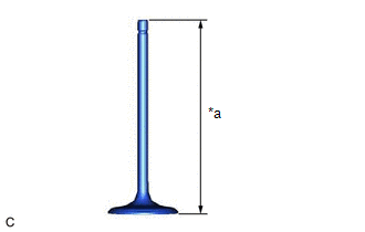
4. INSPECT EXHAUST VALVE
(a) Using a micrometer, measure the diameter of the valve stem. Standard Valve Stem Diameter: 5.465 to 5.480 mm (0.215 to 0.216 in.) HINT: If the valve stem diameter is not as specified, check the exhaust valve guide bush oil clearance. |
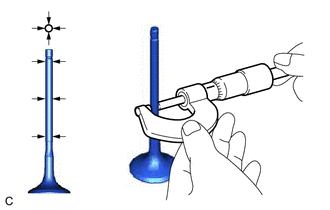 |
(b) Using a vernier caliper, measure the valve head margin thickness. Standard Margin Thickness: 1.0 mm (0.0394 in.) Minimum Margin Thickness: 0.5 mm (0.0197 in.) HINT: If the margin thickness is less than the minimum, replace the exhaust valve. |
|
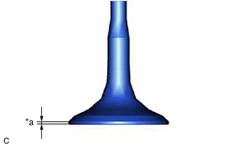
(c) Using a vernier caliper, measure the overall length of the exhaust valve. Standard Overall Length: 110.40 mm (4.35 in.) Minimum Overall Length: 109.90 mm (4.33 in.) HINT: If the overall length is less than the minimum, replace the exhaust valve. |
|
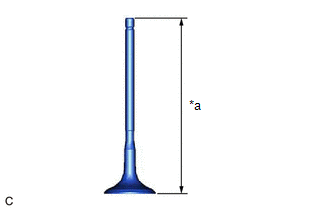
5. INSPECT INTAKE VALVE SEAT
(a) Apply a light coat of Prussian blue to the valve face.
(b) Lightly press the valve face against the intake valve seat.
NOTICE:
Do not rotate the intake valve while pressing it.
(c) Check the valve face and intake valve seat by using the following procedure: (1) If Prussian blue appears 360° around the entire intake valve face, the valve face is concentric. HINT: If the valve face is not concentric, replace the intake valve. (2) If Prussian blue appears 360° around the entire intake valve seat, the intake valve seat and valve face are concentric. HINT: If the valve face is not concentric, resurface the intake valve seat. (3) Measure the width of the contact area of the intake valve seat and valve face. Standard Width: 1.1 to 1.5 mm (0.0433 to 0.0591 in.) |
|
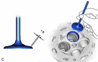
6. INSPECT EXHAUST VALVE SEAT
(a) Apply a light coat of Prussian blue to the valve face.
(b) Lightly press the valve face against the exhaust valve seat.
NOTICE:
Do not rotate the exhaust valve while pressing it.
(c) Check the valve face and exhaust valve seat by using the following procedure: (1) If Prussian blue appears 360° around the entire exhaust valve face, the valve face is concentric. HINT: If the valve face is not concentric, replace the exhaust valve. (2) If Prussian blue appears 360° around the entire exhaust valve seat, the exhaust valve seat and valve face are concentric. HINT: If the valve face is not concentric, resurface the exhaust valve seat. (3) Measure the width of the contact area of the exhaust valve seat and valve face. Standard Width: 1.1 to 1.5 mm (0.0433 to 0.0591 in.) |
|
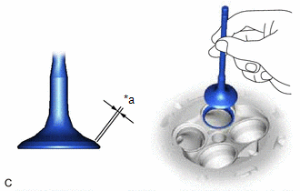
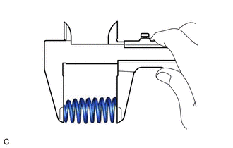
7. INSPECT INNER COMPRESSION SPRING
(a) Using a vernier caliper, measure the free length of the inner compression spring. Standard Free Length: 54.53 mm (2.15 in.) Minimum Free Length: 52.43 mm (2.06 in.) HINT: If the free length is not as specified, replace the inner compression spring. |
 |
(b) Using a steel square, measure the deviation of the inner compression spring. Maximum Deviation (Reference): 1.4 mm (0.0551 in.) HINT: If the deviation is more than the maximum, replace the inner compression spring. |
|
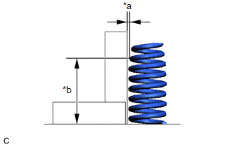
8. INSPECT VALVE GUIDE BUSH OIL CLEARANCE
(a) Using a caliper gauge, measure the inside diameter of the valve guide bush. Standard Valve Guide Bush Inside Diameter: 5.510 to 5.530 mm (0.217 to 0.218 in.) |
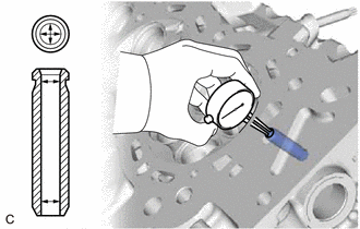 |
(b) Subtract the valve stem diameter measurement from the valve guide bush inside diameter measurement.
Standard Oil Clearance:
Item | Specified Condition |
|---|---|
Intake |
0.025 to 0.060 mm (0.000984 to 0.00236 in.) |
Exhaust |
0.030 to 0.065 mm (0.00118 to 0.00256 in.) |
Maximum Oil Clearance:
Item | Specified Condition |
|---|---|
Intake |
0.12 mm (0.00472 in.) |
Exhaust |
0.12 mm (0.00472 in.) |
HINT:
If the oil clearance is more than the maximum, replace the valve and valve guide bush.
Precaution
PRECAUTION
HINT:
- Any digits beyond the 1/100 mm (1/1000 in.) place for standard, minimum and maximum values should be used as a reference only.
- When both standard and maximum or minimum values are listed for an inspection, use the standard value as a reference only and base any judgments on the maximum and minimum values.
Reassembly
REASSEMBLY
HINT:
- Use the same procedure for bank 1 and bank 2.
- The following procedure is for bank 2.
PROCEDURE
1. INSTALL SPARK PLUG TUBE
HINT:
When using a new cylinder head LH, the spark plug tubes must be replaced.
(a) Apply adhesive to a new spark plug tube as shown in the illustration. Adhesive: Toyota Genuine Adhesive 1324, Three Bond 1324 or equivalent Standard Application Width: 1.0 to 3.0 mm (0.0394 to 0.118 in.) NOTICE: Install the spark plug tube within 3 minutes of applying adhesive. |
|
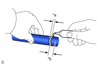
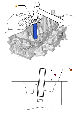
(b) Using a hammer and wooden block, tap in the 3 spark plug tubes to the specified protrusion height. Standard Protrusion Height: 73 mm (2.87 in.) NOTICE:
|
|
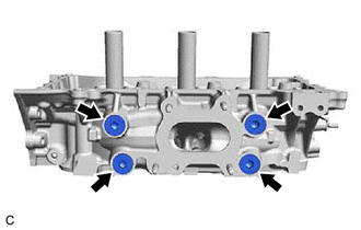
2. INSTALL NO. 3 STRAIGHT SCREW PLUG
(a) Using a 10 mm hexagon socket wrench, install 4 new cylinder head screw plug gaskets and the 4 No. 3 straight screw plugs to the cylinder head LH. Torque: 65 N·m {663 kgf·cm, 48 ft·lbf} NOTICE:
|
 |
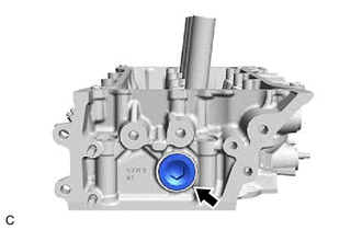
3. INSTALL NO. 2 STRAIGHT SCREW PLUG
(a) Using a 14 mm hexagon wrench, install a new cylinder head screw plug gasket and the No. 2 straight screw plug to the cylinder head LH. Torque: 80 N·m {816 kgf·cm, 59 ft·lbf} |
 |
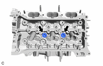
4. INSTALL NO. 1 STRAIGHT SCREW PLUG
(a) Apply adhesive to the 2 No. 1 straight screw plugs.
Adhesive:
Toyota Genuine Adhesive 1324, Three Bond 1324 or equivalent
NOTICE:
Install the 2 No. 1 straight screw plugs within 3 minutes of applying adhesive.
(b) Using a 10 mm hexagon socket wrench, install 2 new water hole gaskets and the 2 No. 1 straight screw plugs to the cylinder head LH. Torque: 44 N·m {449 kgf·cm, 32 ft·lbf} |
 |
5. INSTALL VALVE SPRING SEAT
(a) Install the 12 valve spring seats to the cylinder head LH.
6. INSTALL INTAKE VALVE STEM OIL SEAL
(a) Apply a light coat of engine oil to a new intake valve stem oil seal. NOTICE: Make sure to install each valve stem oil seal to the correct side. Installing an intake valve stem oil seal to the exhaust side or installing an exhaust valve stem oil seal to the intake side can cause installation problems later. HINT: The intake valve stem oil seals are gray and the exhaust valve stem oil seals are black. |
|
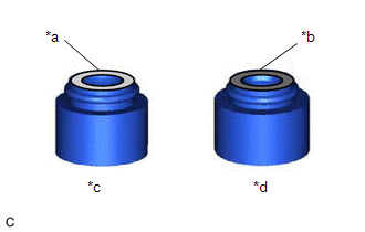
(b) Using SST, push in the 6 intake valve stem oil seals to the intake valve guide bush. SST: 09201-41020 NOTICE:
|
|
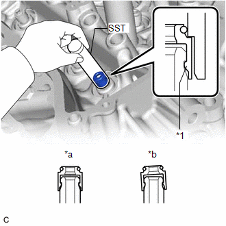
7. INSTALL EXHAUST VALVE STEM OIL SEAL
HINT:
Use the same procedure as for the intake side.
8. INSTALL EXHAUST VALVE
(a) Sufficiently apply engine oil to the tip area of the exhaust valve shown in the illustration. |
|
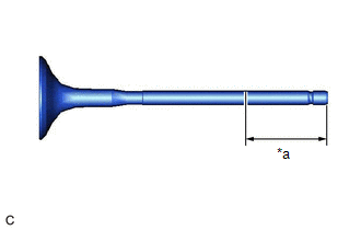
(b) Install the 6 exhaust valves, 6 inner compression springs and 6 valve spring retainers to the cylinder head LH.
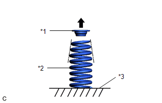
*1 |
Valve Spring Retainer |
*2 |
Inner Compression Spring |
*3 |
Cylinder Head LH |
 |
Top Side |
NOTICE:
- Install the inner compression spring with its tapered side facing upward (towards the valve spring retainer).
- Install the same parts in the same combination to their original locations.
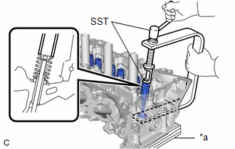
(c) Using SST and wooden blocks, compress the inner compression spring and install the 6 valve spring retainer locks to the valve spring retainer. SST: 09202-70020 09202-01010 09202-01020 SST: 09202-00021 NOTICE: Install the same parts in the same combination to their original locations. |
|
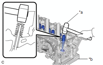
(d) Using a plastic hammer, lightly tap the valve stem tip to ensure a proper fit. NOTICE:
|
|
9. INSTALL INTAKE VALVE
(a) Sufficiently apply engine oil to the tip area of the intake valve shown in the illustration. |
|
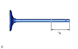
(b) Install the 6 intake valves, 6 inner compression springs and 6 valve spring retainers to the cylinder head LH.
*1 |
Valve Spring Retainer |
*2 |
Inner Compression Spring |
*3 |
Cylinder Head LH |
|
Top Side |
NOTICE:
- Install the inner compression spring with its tapered side facing upward (towards the valve spring retainer).
- Install the same parts in the same combination to their original locations.
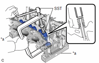
(c) Using SST and wooden blocks, compress the inner compression spring and install the 6 valve spring retainer locks to the valve spring retainer. SST: 09202-70020 09202-01010 09202-01020 SST: 09202-00021 NOTICE: Install the same parts in the same combination to their original locations. |
|
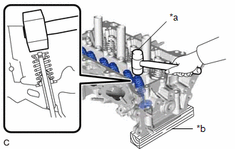
(d) Using a plastic hammer, lightly tap the valve stem tip to ensure a proper fit. NOTICE:
|
|
Repair
REPAIR
HINT:
- Use the same procedure for bank 1 and bank 2.
- The following procedure is for bank 2.
PROCEDURE
1. REPAIR INTAKE VALVE SEAT
NOTICE:
- While repairing the intake valve seat, make sure to constantly check the valve seat width and valve seating position.
- Release the cutter gradually to make the intake valve seat smooth.
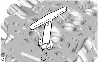
(a) Using a 45° cutter, resurface the intake valve seat so that the intake valve seat width is more than the standard. |
 |
(b) Using 30° and 60° cutters, correct the intake valve seat so that the intake valve contacts the entire circumference of the intake valve seat. The contact should be in the center of the intake valve seat, and the intake valve seat width should be as specified around the entire circumference of the intake valve seat. Standard Width: 1.1 to 1.5 mm (0.0433 to 0.0591 in.) |
|
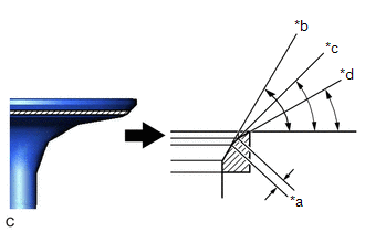
(c) Hand lap the intake valve and intake valve seat with an abrasive compound.
(d) Check the intake valve seating position.
2. REPAIR EXHAUST VALVE SEAT
NOTICE:
- While repairing the exhaust valve seat, make sure to constantly check the valve seat width and valve seating position.
- Release the cutter gradually to make the exhaust valve seat smooth.
(a) Using a 45° cutter, resurface the exhaust valve seat so that the exhaust valve seat width is more than the standard. |
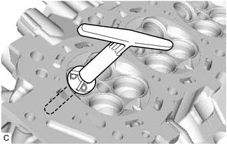 |
(b) Using 30° and 75° cutters, correct the exhaust valve seat so that the exhaust valve contacts the entire circumference of the exhaust valve seat. The contact should be in the center of the exhaust valve seat, and the exhaust valve seat width should be as specified around the entire circumference of the exhaust valve seat. Standard Width: 1.1 to 1.5 mm (0.0433 to 0.0591 in.) |
|
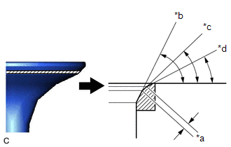
(c) Hand lap the exhaust valve and exhaust valve seat with an abrasive compound.
(d) Check the exhaust valve seating position.
Replacement
REPLACEMENT
HINT:
- Use the same procedure for bank 1 and bank 2.
- The following procedure is for bank 2.
PROCEDURE
1. REPLACE INTAKE VALVE GUIDE BUSH
(a) Heat the cylinder head LH to between 80 and 100 °C.
(b) Place the cylinder head LH on wooden blocks.
CAUTION:
Be sure to wear protective gloves.
(c) Using SST and a hammer, tap out the intake valve guide bush. SST: 09201-10000 09201-01050 SST: 09950-70010 09951-07100 |
|
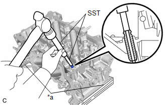
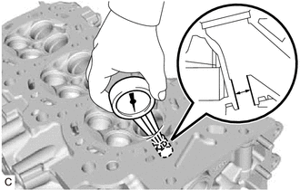
(d) Using a caliper gauge, measure the intake valve guide bush bore diameter of the cylinder head LH. Standard Intake Valve Guide Bush Bore Diameter: 10.285 to 10.306 mm (0.405 to 0.406 in.) New Guide Bush Selection Chart:
HINT:
|
 |
(e) Heat the cylinder head LH to between 80 and 100 °C.
(f) Place the cylinder head LH on wooden blocks.
CAUTION:
Be sure to wear protective gloves.
(g) Using SST and a hammer, tap in a new intake valve guide bush to the specified protrusion height. SST: 09201-10000 09201-01050 SST: 09950-70010 09951-07100 Standard Protrusion Height: 9.30 to 9.70 mm (0.366 to 0.382 in.) |
|
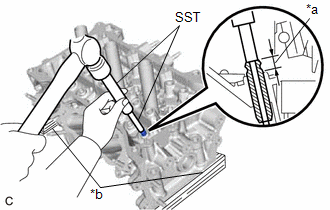
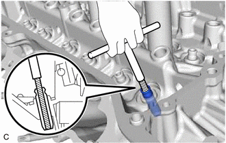
(h) Using a sharp 5.5 mm reamer, ream the intake valve guide bush to obtain the specified oil clearance. Standard Oil Clearance: 0.025 to 0.060 mm (0.000984 to 0.00236 in.) |
 |
2. REPLACE EXHAUST VALVE GUIDE BUSH
(a) Heat the cylinder head LH to between 80 and 100 °C.
(b) Place the cylinder head LH on wooden blocks.
CAUTION:
Be sure to wear protective gloves.
(c) Using SST and a hammer, tap out the exhaust valve guide bush. SST: 09201-10000 09201-01050 SST: 09950-70010 09951-07100 |
|
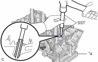
(d) Using a caliper gauge, measure the exhaust valve guide bush bore diameter of the cylinder head LH. Standard Exhaust Valve Guide Bush Bore Diameter: 10.285 to 10.306 mm (0.405 to 0.406 in.) New Guide Bush Selection Chart:
HINT:
|
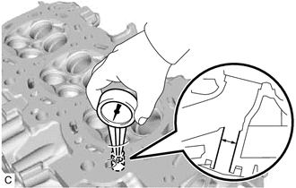 |
(e) Heat the cylinder head LH to between 80 and 100 °C.
(f) Place the cylinder head LH on wooden blocks.
CAUTION:
Be sure to wear protective gloves.
(g) Using SST and a hammer, tap in a new exhaust valve guide bush to the specified protrusion height. SST: 09201-10000 09201-01050 SST: 09950-70010 09951-07100 Standard Protrusion Height: 9.30 to 9.70 mm (0.366 to 0.382 in.) |
|
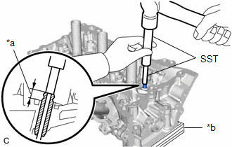
(h) Using a sharp 5.5 mm reamer, ream the exhaust valve guide bush to obtain the specified oil clearance. Standard Oil Clearance: 0.030 to 0.065 mm (0.00118 to 0.00256 in.) |
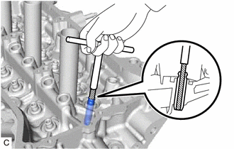 |
3. REPLACE RING PIN
NOTICE:
It is not necessary to remove the ring pins unless they are being replaced.
(a) Using a plastic hammer, tap in new ring pins to the cylinder head LH and cylinder head sub-assembly.
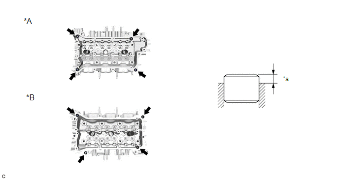
*A |
for Bank 1 |
*B |
for Bank 2 |
*a |
Protrusion Height |
- |
- |
Standard Protrusion Height:
2.5 to 3.5 mm (0.0984 to 0.138 in.)
4. REPLACE STUD BOLT
NOTICE:
If a stud bolt is deformed or its threads are damaged, replace it.
(a) Using E6 and E8 "TORX" socket wrenches, install the stud bolts to the cylinder head LH.
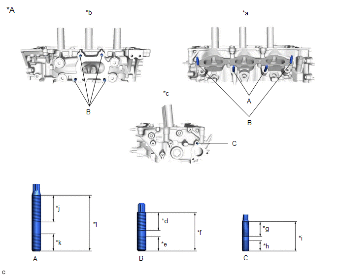
*A |
for Bank 2 |
- |
- |
*a |
Intake Side |
*b |
Exhaust Side |
*c |
Rear Side |
*d |
20 mm (0.787 in.) |
*e |
13 mm (0.512 in.) |
*f |
35 mm (1.38 in.) |
*g |
16 mm (0.630 in.) |
*h |
9 mm (0.354 in.) |
*i |
27 mm (1.06 in.) |
*j |
26 mm (1.02 in.) |
*k |
16.7 mm (0.657 in.) |
*l |
51.7 mm (2.04 in.) |
Torque:
Bolt (A), (B) :
10 N·m {102 kgf·cm, 7 ft·lbf}
Bolt (C) :
4 N·m {41 kgf·cm, 35 in·lbf}
(b) Using E6 and E8 "TORX" socket wrenches, install the stud bolts to the cylinder head sub-assembly.
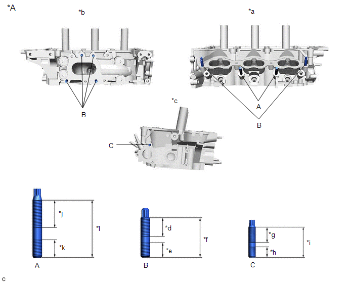
*A |
for Bank 1 |
- |
- |
*a |
Intake Side |
*b |
Exhaust Side |
*c |
Rear Side |
*d |
20 mm (0.787 in.) |
*e |
13 mm (0.512 in.) |
*f |
35 mm (1.38 in.) |
*g |
16 mm (0.630 in.) |
*h |
9 mm (0.354 in.) |
*i |
27 mm (1.06 in.) |
*j |
26 mm (1.02 in.) |
*k |
16.7 mm (0.657 in.) |
*l |
51.7 mm (2.04 in.) |
Torque:
Bolt (A), (B) :
10 N·m {102 kgf·cm, 7 ft·lbf}
Bolt (C) :
4 N·m {41 kgf·cm, 35 in·lbf}
5. REPLACE STRAIGHT PIN
NOTICE:
If a straight pin is deformed, replace it.
(a) Using a plastic hammer, tap in new straight pins to the cylinder head LH as shown in the illustration.
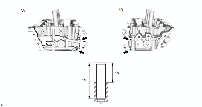
*A |
for Bank 1 |
*B |
for Bank 2 |
*a |
34 mm (1.34 in.) |
*b |
Protrusion Height |
Standard Protrusion Height:
17.5 to 19.5 mm (0.689 to 0.768 in.)