Carburetor Diagnosis, Disassembly and Adjustment
GENERAL INFORMATION
Before concluding that the carburetor is faulty, check ignition timing, spark plug and valve clearances, and cylinder compression.If these checks do not reveal the cause of poor engine operation, remove the carburetor for cleaning and repair.
Carburetor disassembly is usually required very rarely. In most cases, only cleaning of the jets and internal passages is required.
Disassembly
PROCEDURE
1. Disconnect the spring from the throttle valve and check the wear of the accelerator pump lever.
2. Remove the spring, the spring washer and the retaining ring, and remove the lever.
3. Disconnect the choke valve rod.
4. Unscrew the screws and carefully remove the upper body section.
5. Check the float chamber for contamination.
6. Remove the first accelerator pump spring, the retaining ring, the filter, and take out the ball.
7. Unscrew the plug and take out the second accelerator pump spring, the counterweight (check valve), and the ball.
8. Remove the pump plunger and check the wear of the plunger and cylinder.
9. Drive out the float pin, remove the float, the needle valve and the float chamber gasket (on some carburetors the needle valve seat is not removed).
10. Before disassembly, note the location of all jets.
11. Unscrew all fuel and air jets from both chambers. Do not unscrew the secondary chamber idle air jets.
12. Unscrew the plugs and idle jets from the center body section.
13. Unscrew the screws and remove the small venturis, then take out the emulsion tubes.
14. Unscrew the primary chamber main jet from the float chamber wall.
15. Unscrew the secondary chamber main jet.
16. Remove the restrictor sleeve and screw in the screw until it contacts the seat, counting the number of turns.
17. Unscrew the screw completely.
18. If necessary, unscrew the valve coils, and carefully remove the seals and springs.
19. Check the coils: when 12 V is applied, the plungers should be pulled in.
20. On vehicles with a catalytic converter, if necessary, remove the mixture control solenoid valve. To do this, disconnect the wire, unscrew the screws and remove the valve.
21. Clean the jets using special cleaning agents. Blowing with compressed air is not recommended, as it may damage the carburetor diaphragms.
22. Wash the body parts.
23. Check the body section mating surfaces for distortion.
24. If it is necessary to remove an electrical component of the carburetor, disconnect the wire of this component from the connector.
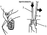
25. To do this, use a thin screwdriver (1, 4) to push back the terminal tab (5) and push out the terminal with the wire (2). First remove the retaining ring at the rear of the connector.
26. Mark each wire.
27. When assembling, replace worn parts and the entire set of gaskets and seals.
28. Assembly is performed in the reverse order.
29. Do not tighten the jets with excessive force.
30. Before installing the carburetor, perform the necessary adjustments.
Adjusting idle speed and mixture quality. See subsection 2.2.2.
Adjusting the Fuel Level in the Float Chamber

The arrow indicates the sight glass in the carburetor body.
Note: The fuel level in the float chamber can be checked through the sight glass. At idle, the level should be between the two marks.
PROCEDURE
1. Adjusting the level is performed as follows.
2. Raise and lower the float onto the needle valve, and measure the distance between the float and the carburetor body mating surface.
3. If the distance differs from the specification, adjust it by carefully bending the float arm.
4. Turn the carburetor body over and check the distance between the lower edge of the float and the parting surface.
5. If the distance differs from the specification, adjust it by carefully bending the float stop tab.
Adjusting the Throttle Valve Opening Angle
PROCEDURE
1. Unscrew the three screws and remove the thermo-electric actuator and the ring.
2. Turn the carburetor over, slightly open the throttle valve, and move the fast idle lever to the second step of the cam. The throttle valve will be slightly open due to the adjusting screw.
3. Make sure the choke valve is fully closed.
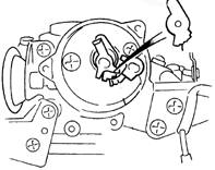
4. Move the fast idle lever to the second step of the cam.
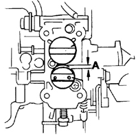
5. Using a drill gauge, check the clearance (A) between the throttle valve and the chamber wall.
6. If necessary, set the clearance by turning the adjusting screw.
7. Install the ring and the thermo-electric actuator.
8. Align the marks on the actuator cover and on the choke valve housing, and tighten the screws.

Adjusting the Choke Valve
1. Tab
2. Vacuum pump
3. Vacuum diaphragm unit
4. Diaphragm
5. Clearance
PROCEDURE
1. Pull the linkage and fully close the choke valve.
2. Fully push the rod into the diaphragm using a screwdriver, or create a vacuum in the diaphragm.
3. Using a drill gauge, check the clearance between the choke valve and the chamber wall. (At temperatures below 5 °C, use the clearance value for position 1 as the reference; above 16.5 °C, use the value for position 2.)
4. If necessary, adjust the clearance by bending the tab.
Test yourself
A quick Nissan Sunny quiz: every answer comes with an explanation and a link to the manual page.