Exhaust Gas Oxidation System
GENERAL INFORMATION
The exhaust gas oxidation system reduces hydrocarbon and CO emissions by injecting filtered air into the exhaust manifold. Gases are additionally oxidized before entering the catalytic converter. The system includes a solenoid valve.To check the solenoid valve, remove it (see below).
Inspection
PROCEDURE
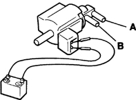
1. When power (12 V) is applied, air must flow freely through ports A and B.
2. If the check result is negative, replace the valve.
3. Remove the air injection valve (see below).
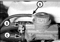
4. When air is blown through port B, air must not pass through. If vacuum is applied to port A, air must pass from B to C; air must not pass in the reverse direction (from C to B) under any conditions. (A – vacuum hose from solenoid valve, B – hose from air cleaner, C – to exhaust manifold.)
5. If the check result is negative, replace the valve.
SOLENOID VALVE Replacement
PROCEDURE
1. The solenoid valve is screwed into the left side of the intake manifold.
2. Disconnect the battery ground cable, then disconnect the connector.
3. Mark the connection order of all hoses.
4. Loosen the clamps and disconnect the hoses.
5. Remove the valve from the bracket.
6. Installation is the reverse of removal.
AIR INJECTION VALVE Replacement
PROCEDURE
1. The air injection valve is mounted on the left suspension cover.

2. To replace the valve, disconnect the hoses (indicated by arrows).
3. Unscrew the bolts and remove the valve.
4. Installation is performed in the reverse order.
IDLE CORRECTION VALVE Check
PROCEDURE

1. Remove the air cleaner cover. The idle correction valve(s) (indicated by arrow) are mounted in the bottom of the filter housing.
2. Prepare a thermometer and a heat gun. Heat the valve with the heat gun. The valve must be closed at temperatures below 55 °C, begin to open in the range of 55–65 °C, and fully open above 65 °C. If two valves are provided, the temperature characteristics of one valve are exactly the same, and the second valve is closed below 65 °C, begins to open in the range of 65–75 °C, and fully opens above 75 °C. When fully cooled, the valve must close completely.
3. If the check results are negative, replace the valve.
Correction Valve Replacement
PROCEDURE
1. Remove the air filter.
2. Disconnect the hose, unscrew the screws and remove the valve.
3. Install the valve in the reverse order.
GAS SHOCK ABSORBER Check When the gas shock absorber rod is pushed in, resistance must be felt, and when released, the rod must quickly return to its original position.
Otherwise, replace the gas shock absorber.
Replacement
PROCEDURE
1. On carbureted engines, remove the 2 screws and remove the valve from the carburetor.
2. On fuel-injected engines, remove the nut and take the valve out of the throttle body bracket.
3. Install the gas shock absorber in the reverse order and check the adjustment. On a warm engine, the gas shock absorber rod must contact the adjusting screw at 1900±200 rpm. To adjust, loosen the locknut and set the screw to the required position at the specified speed, then check the adjustment again.
Test yourself
A quick Nissan Sunny quiz: every answer comes with an explanation and a link to the manual page.