Dtc/circuit Diagnosis (C1f00-1c Control Unit ... C1f04-61 Brake Sw/stop Lamp Sw)
- C1f00-1c Control Unit
- C1f00-44 Control Unit
- C1f00-4b Control Unit
- C1f00-54 Hands Off Threshold Incomplete
- C1f02-16 Power Supply Circuit
- C1f07-62 Operation Sw Circ
- C1f03-23 Operation Sw Circ
- C1f03-72 Stop Lamp Relay
- C1f04-48 Feb Ope Count Limit
- C1f04-61 Brake Sw/stop Lamp Sw
C1f00-1c Control Unit Nissan Pathfinder 2022
DTC Description
DTC DETECTION LOGIC
| DTC | CONSULT screen terms (Trouble diagnosis content) | DTC detection condition | ||
|---|---|---|---|---|
| C1F00 | 1C | CONTROL UNIT (Control unit) |
Diagnosis condition | When engine is running |
| Signal (terminal) | — | |||
| Threshold | ADAS control unit 2 internal malfunction | |||
| Diagnosis delay time | 1 second or less | |||
POSSIBLE CAUSE
ADAS control unit 2
FAIL-SAFE
The following systems are canceled.
Vehicle-to-vehicle distance control mode
Conventional (fixed speed) cruise control mode
Steering wheel assistance function
AEB
RAB
I-FCW
LDW
I-LI
I-BSI
TSR
I-DA
Confirmation Procedure
PERFORM DTC CONFIRMATION PROCEDURE
Start the engine.
Perform “All DTC Reading” with CONSULT.
Check if the “C1F00-1C” is detected as the current malfunction in “Self Diagnostic Result” of “ICC/ADAS 2”.
Is DTC “C1F00-1C” detected?
YES-1>>“CRNT” is displayed: Refer to DTC Diagnosis Procedure.
YES-2>>“PAST” is displayed: Check the 12V battery. Refer to Work Flow.
NO-1 >>To check malfunction symptom before repair: Refer to Intermittent Incident.
NO-2 >>Confirmation after repair: INSPECTION END
DTC Diagnosis Procedure
CHECK SELF-DIAGNOSIS RESULTS
Check if any DTC other than “C1F00-XX”, is detected in “Self Diagnostic Result” of “ICC/ADAS 2”.
Is any DTC detected?
YES>>Perform diagnosis on the detected DTC and repair or replace the malfunctioning parts. Refer to DTC Index.
NO>>GO TO 2.
CHECK 12V BATTERY
Check 12V battery. Refer to Work Flow.
Is the inspection result normal?
YES>>GO TO 3.
NO>>Repair or replace the 12V battery. Refer to Removal and Installation.
PERFORM THE SELF-DIAGNOSIS
 CONSULT
Ignition switch OFF (Auto ACC function ON).
Get out of the Nissan Pathfinder vehicle, close all doors (other than hood), check that the combination meter is OFF, and wait for 1 minute or more without opening these doors.
Ignition switch ON without depressing the brake pedal.
Perform self-diagnosis for “ICC/ADAS 2”.
Is “C1F00-1C” detected as the current malfunction?
YES>>Replace the ADAS control unit 2. Refer to Removal and Installation.
NO>>Inspection End. (Erase the memory of self-diagnosis results.)
C1f00-44 Control Unit Nissan Pathfinder 2026
DTC Description
DTC DETECTION LOGIC
| DTC | CONSULT screen terms (Trouble diagnosis content) | DTC detection condition | ||
|---|---|---|---|---|
| C1F00 | 44 | CONTROL UNIT (Control unit) |
Diagnosis condition | When engine is running |
| Signal (terminal) | — | |||
| Threshold | ADAS control unit 2 internal malfunction | |||
| Diagnosis delay time | 1 second or less | |||
POSSIBLE CAUSE
ADAS control unit 2
FAIL-SAFE
The following systems are canceled.
Vehicle-to-vehicle distance control mode
Conventional (fixed speed) cruise control mode
Steering wheel assistance function
AEB
RAB
I-FCW
LDW
I-LI
I-BSI
TSR
I-DA
CONFIRMATION PROCEDURE
PERFORM DTC CONFIRMATION PROCEDURE
Start the engine.
Perform “All DTC Reading” with CONSULT.
Check if the “C1F00-44” is detected as the current malfunction in “Self Diagnostic Result” of “ICC/ADAS 2”.
Is “C1F00-44” detected as the current malfunction?
YES>>Refer to DTC Diagnosis Procedure.
NO-1 >>To check malfunction symptom before repair: Refer to Intermittent Incident.
NO-2 >>Confirmation after repair: INSPECTION END
DTC Diagnosis Procedure
CHECK SELF-DIAGNOSIS RESULTS
Check if any DTC other than “C1F00-XX”, is detected in “Self Diagnostic Result” of “ICC/ADAS 2”.
Is any DTC detected?
YES>>Perform diagnosis on the detected DTC and repair or replace the malfunctioning parts. Refer to DTC Index.
NO>>Replace the ADAS control unit 2. Refer to Removal and Installation.
C1f00-4b Control Unit Nissan Pathfinder SUV
DTC Description
DTC DETECTION LOGIC
| DTC | CONSULT screen terms (Trouble diagnosis content) | DTC detection condition | ||
|---|---|---|---|---|
| C1F00 | 4B | CONTROL UNIT (Control unit) |
Diagnosis condition |
|
| Signal (terminal) | — | |||
| Threshold | Temperature detected by the temperature sensor integrated in ADAS control unit 2 remains more than 105 °C | |||
| Diagnosis delay time | 5 seconds or more | |||
POSSIBLE CAUSE
Temperature around the ADAS control unit 2 becomes extremely high
FAIL-SAFE
The following systems are canceled.
Vehicle-to-vehicle distance control mode
Conventional (fixed speed) cruise control mode
Steering wheel assistance function
AEB
RAB
I-FCW
LDW
I-LI
I-BSI
TSR
I-DA
CONFIRMATION PROCEDURE
PERFORM DTC CONFIRMATION PROCEDURE
Turn the ignition switch OFF.
Wait for 10 minutes or more.
Start the engine.
Turn the AEB system ON.
Perform “All DTC Reading” with CONSULT.
Check if the “C1F00-4B” is detected as the current malfunction in “Self Diagnostic Result” of “ICC/ADAS 2”.
Is “C1F00-4B” detected as the current malfunction?
YES>>Refer to DTC Diagnosis Procedure.
NO-1 >>To check malfunction symptom before repair: Refer to Intermittent Incident.
NO-2 >>Confirmation after repair: INSPECTION END
DTC Diagnosis Procedure
CHECK ENGINE COOLING SYSTEM
Check for any malfunctions in engine cooling system.
Is engine cooling system normal?
YES>>Replace the ADAS control unit 2. Refer to Removal and Installation.
NO>>Repair engine cooling system.
C1f00-54 Hands Off Threshold Incomplete Nissan Pathfinder 2026
DTC Description
DTC DETECTION LOGIC
| DTC | CONSULT screen terms (Trouble diagnosis content) | DTC detection condition | ||
|---|---|---|---|---|
| C1F00 | 54 | CONTROL UNIT (Control unit) |
Diagnosis condition | — |
| Signal (terminal) | — | |||
| Threshold | Steering Torque Calibration is not completed | |||
| Diagnosis delay time | — | |||
POSSIBLE CAUSE
Steering Torque Calibration is not adjusted
Steering Torque Calibration has been interrupted
FAIL-SAFE
Vehicle-to-vehicle distance control mode
Conventional (fixed speed) cruise control mode
Steering wheel assistance function
CONFIRMATION PROCEDURE
PERFORM DTC CONFIRMATION PROCEDURE
 CONSULT
Start the engine.
Perform “All DTC Reading”.
Check if the “C1F00F-54” is detected as the current malfunction in “Self Diagnostic Result” of “ICC/ADAS 2”.
Is “C1F00-54” detected as the current malfunction?
YES>>Refer to DTC Diagnosis Procedure.
NO-1>>To check malfunction symptom before repair: Refer to Intermittent Incident.
NO-2>>Confirmation after repair: Inspection End
DTC Diagnosis Procedure
STEERING TORQUE CALIBRATION
 CONSULT
Perform Steering Torque Calibration. Refer to Work Procedure.
Erase all self-diagnosis results.
Perform "All DTC Reading".
Check if "C1F00-54" is detected in "self-diagnosis result" of "ICC/ADAS 2".
Is “C1F00-54” detected?
YES>>Replace the ADAS control unit 2. Then perform Steering Torque Calibration again. Refer to Removal and Installation.
NO>>INSPECTION END.
C1f02-16 Power Supply Circuit Nissan Pathfinder 5th Gen
DTC Description
DTC DETECTION LOGIC
| DTC | CONSULT screen terms (Trouble diagnosis content) | DTC detection condition | ||
|---|---|---|---|---|
| C1F02 | 16 | POWER SUPPLY CIR (Power supply circuit) |
Diagnosis condition |
|
| Signal (terminal) | Battery power supply | |||
| Threshold | The battery voltage sent to ADAS control unit 2 remains less than 7.9 V | |||
| Diagnosis delay time | 5 seconds or more | |||
POSSIBLE CAUSE
Connector, harness, fuse
ADAS control unit 2
FAIL-SAFE
The following systems are canceled.
Vehicle-to-vehicle distance control mode
Conventional (fixed speed) cruise control mode
Steering wheel assistance function
AEB
RAB
I-FCW
LDW
I-LI
I-BSI
TSR
I-DA
CONFIRMATION PROCEDURE
PERFORM DTC CONFIRMATION PROCEDURE
Start the engine.
Turn the AEB system ON.
Perform “All DTC Reading” with CONSULT.
Check if the “C1F02-16” is detected as the current malfunction in “Self Diagnostic Result” of “ICC/ADAS 2”.
Is “C1F02-16” detected as the current malfunction?
YES>>Refer to DTC Diagnosis Procedure.
NO-1 >>To check malfunction symptom before repair: Refer to Intermittent Incident.
NO-2 >>Confirmation after repair: INSPECTION END
DTC Diagnosis Procedure
CHECK ADAS CONTROL UNIT 2 POWER SUPPLY AND GROUND CIRCUIT
Check power supply and ground circuit of ADAS control unit 2. Refer to Diagnosis Procedure.
Is the inspection result normal?
YES>>Replace the ADAS control unit 2. Refer to Removal and Installation.
NO>>Repair or replace the malfunctioning parts.
C1f07-62 Operation Sw Circ Nissan Pathfinder Fifth generation
DTC Description
DTC DETECTION LOGIC
| DTC | CONSULT screen terms (Trouble diagnosis content) | DTC detection condition | ||
|---|---|---|---|---|
| C1F07 | 62 | OPERATION SW CIRC | Diagnosis condition | When engine is running |
| Signal (terminal) | Brake switch Signal | |||
| Threshold | If an error occurs in brake switch signal transmitted from ABS actuator and electric unit (control unit) | |||
| Diagnosis delay time | 1 second or less | |||
POSSIBLE CAUSE
Brake pedal
Stop lamp switch
BCM
FAIL-SAFE
The following systems are canceled.
Vehicle-to-vehicle distance control mode
Conventional (fixed speed) cruise control mode
Steering wheel assistance function
AEB
RAB
I-FCW
LDW
I-LI
I-BSI
TSR
CONFIRMATION PROCEDURE
CHECK DTC PRIORITY
If DTC “C1F07–62” is displayed with Network-DTC, first diagnose the Network-DTC.
Is applicable DTC detected?
YES>>Perform diagnosis of applicable. Refer to DTC Index.
NO>>GO TO 2.
PERFORM DTC CONFIRMATION PROCEDURE
Start the engine.
Perform “All DTC Reading” with CONSULT.
Check if "C1F07-62" is detected as the current fault in the "self-diagnostic results" of "ICC/ADAS 2".
Is “C1F07-62” detected as the current malfunction?
YES>>Refer to DTC Diagnosis Procedure.
NO-1>>To check malfunction symptom before repair: Refer to Intermittent Incident.
NO-2>>Confirmation after repair: INSPECTION END
DTC Diagnosis Procedure
CHECK BRAKE PEDAL
Check brake pedal. Refer to Inspection and Adjustment.
Is the inspection result normal?
YES>>GO TO 2.
NO>>Adjust brake pedal. Refer to Inspection and Adjustment.
CHECK STOP LAMP OPERATION
Turn ignition switch ON.
Check stop lamp and high-mounted stop lamp is turned ON when brake pedal is operated.
depressed :stop lamp and high-mounted stop lamp is ON. Fully released :stop lamp and high-mounted stop lamp is OFF.
Is the inspection result normal?
YES>>Stop lamp circuit is nomal. Replace ADAS C/U 2. Refer to Removal and Installation.
NO>>Refer to Diagnosis Procedure.
C1f03-23 Operation Sw Circ Nissan Pathfinder Fifth generation
Without Propilot Assist System
DTC Description
DTC DETECTION LOGIC
| DTC | CONSULT screen terms (Trouble diagnosis content) | DTC detection condition | ||
|---|---|---|---|---|
| C1F03 | 23 | OPERATION SW CIRC (Operation switch circuit) |
Diagnosis condition |
|
| Signal (terminal) | — | |||
| Threshold | Any switch of the ICC steering switch is detected as “ON” | |||
| Diagnosis delay time | Continuously 60 seconds | |||
POSSIBLE CAUSE
ICC steering switch circuit
ICC steering switch
ECM
FAIL-SAFE
The following systems are canceled.
Vehicle-to-vehicle distance control mode
Conventional (fixed speed) cruise control mode
CONFIRMATION PROCEDURE
CHECK DTC PRIORITY
If DTC “C1F03-23” is displayed with Network-DTC, first diagnose the Network-DTC.
Is applicable DTC detected?
YES>>Perform diagnosis of applicable. Refer to DTC Index.
NO>>GO TO 2 .
PERFORM DTC CONFIRMATION PROCEDURE
Start the engine.
Wait for approximately 5 minutes after turning the MAIN switch ON.
Perform “All DTC Reading” with CONSULT.
Check if the “C1F03-23” is detected as the current malfunction in “Self Diagnostic Result” of “ICC/ADAS 2”.
Is “C1F03-23” detected as the current malfunction?
YES>>Refer to DTC Diagnosis Procedure.
NO-1>>To check malfunction symptom before repair: Refer to Intermittent Incident.
NO-2>>Confirmation after repair: INSPECTION END
DTC Diagnosis Procedure
CHECK DTC PRIORITY
If DTC “C1F03-23” is displayed with Network-DTC, first diagnose the Network-DTC.
Is applicable DTC detected?
YES>>Perform diagnosis of applicable. Refer to DTC Index.
NO>>GO TO 2 .
CHECK ICC STEERING SWITCH
Turn the ignition switch OFF.
Disconnect the ICC steering switch connector.
Check the ICC steering switch. Refer to Component Inspection.
Is the inspection result normal?
YES>>GO TO 3.
NO>>Replace the ICC steering switch.
CHECK HARNESS BETWEEN SPIRAL CABLE AND ECM
Disconnect the ECM connector.
Check for continuity between the spiral cable harness connector and ECM harness connector.
Spiral cable ECM Continuity Connector Terminal Connector Terminal M30 8 E32 186 Existed 1 187 Check for continuity between spiral cable harness connector and ground.
Spiral cable Ground Continuity Connector Terminal M30 8 Not existed 1
Is the inspection result normal?
YES>>GO TO 4.
NO>>Repair the harnesses or connectors.
CHECK SPIRAL CABLE
Check for continuity between spiral cable terminals.
| Spiral cable | Continuity | |
| Terminal | ||
| 21 | 8 | Existed |
| 36 | 1 | |
Is the inspection result normal?
YES>>GO TO 5.
NO>>Replace the spiral cable.
PERFORM SELF-DIAGNOSIS OF ECM
Connect the connectors of ICC steering switch and ECM connector.
Turn the ignition switch ON.
Perform “All DTC Reading”.
Check if any DTC is detected in “Self Diagnostic Result” of “ENGINE”.
Is any DTC detected?
YES>>Perform self-diagnosis on the detected DTC and repair or replace the malfunctioning parts. Refer to DTC Index .
NO>>Replace the ADAS control unit 2. Refer to Removal and Installation.
Component Inspection
CHECK ICC STEERING SWITCH
Check resistance between ICC steering switch terminals.
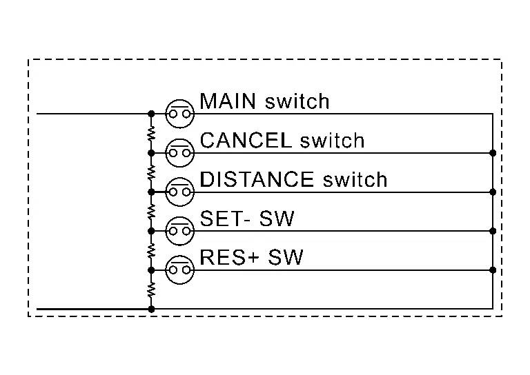
| Terminal | Switch operation | Resistance [Ω] | |
|---|---|---|---|
| 21 | 36 | When pressing MAIN switch | Approx. 0 |
| When pressing CANCEL switch | Approx. 309 | ||
| When pressing DISTANCE switch | Approx. 741 | ||
| When pressing SET- switch | Approx. 1406 | ||
| When pressing RES+ switch | Approx. 2586 | ||
| When all switches are not pressed | Approx. 5456 | ||
Is the inspection result normal?
YES>>INSPECTION END
NO>>Replace the ICC steering switch.
With Propilot Assist System
DTC Description
DTC DETECTION LOGIC
| DTC | CONSULT screen terms (Trouble diagnosis content) | DTC detection condition | ||
|---|---|---|---|---|
| C1F03 | 23 | OPERATION SW CIRC (Operation switch circuit) |
Diagnosis condition |
|
| Signal (terminal) | — | |||
| Threshold | Any switch of the ProPILOT Assist steering switch is detected as “ON” | |||
| Diagnosis delay time | Continuously 60 seconds | |||
POSSIBLE CAUSE
ProPILOT Assist steering switch circuit
ProPILOT Assist steering switch
ECM
FAIL-SAFE
The following systems are canceled.
Vehicle-to-vehicle distance control mode
Conventional (fixed speed) cruise control mode
Steering wheel assistance function
CONFIRMATION PROCEDURE
CHECK DTC PRIORITY
If DTC “C1F03-23” is displayed with Network-DTC, first diagnose the Network-DTC.
Is applicable DTC detected?
YES>>Perform diagnosis of applicable. Refer to DTC Index.
NO>>GO TO 2 .
PERFORM DTC CONFIRMATION PROCEDURE
Start the engine.
Wait for approximately 5 minutes after turning the ProPILOT Assist MAIN switch ON.
Perform “All DTC Reading” with CONSULT.
Check if the “C1F03-23” is detected as the current malfunction in “Self Diagnostic Result” of “ICC/ADAS 2”.
Is “C1F03-23” detected as the current malfunction?
YES>>Refer to DTC Diagnosis Procedure.
NO-1>>To check malfunction symptom before repair: Refer to Intermittent Incident.
NO-2>>Confirmation after repair: INSPECTION END
DTC Diagnosis Procedure
CHECK DTC PRIORITY
If DTC “C1F03-23” is displayed with Network-DTC, first diagnose the Network-DTC.
Is applicable DTC detected?
YES>>Perform diagnosis of applicable. Refer to DTC Index.
NO>>GO TO 2 .
CHECK ProPILOT ASSIST STEERING SWITCH
Turn the ignition switch OFF.
Disconnect the ProPILOT Assist steering switch connector.
Check the ProPILOT Assist steering switch. Refer to Component Inspection.
Is the inspection result normal?
YES>>GO TO 3.
NO>>Replace the ProPILOT Assist steering switch.
CHECK HARNESS BETWEEN SPIRAL CABLE AND ECM
Disconnect the ECM connector.
Check for continuity between the spiral cable harness connector and ECM harness connector.
Spiral cable ECM Continuity Connector Terminal Connector Terminal M30 8 E32 186 Existed 1 187 Check for continuity between spiral cable harness connector and ground.
Spiral cable Ground Continuity Connector Terminal M30 8 Not existed 1
Is the inspection result normal?
YES>>GO TO 4.
NO>>Repair the harnesses or connectors.
CHECK SPIRAL CABLE
Check for continuity between spiral cable terminals.
| Spiral cable | Continuity | |
| Terminal | ||
| 21 | 8 | Existed |
| 36 | 1 | |
Is the inspection result normal?
YES>>GO TO 5.
NO>>Replace the spiral cable.
PERFORM SELF-DIAGNOSIS OF ECM
Connect the connectors of ProPILOT Assist steering switch and ECM connector.
Turn the ignition switch ON.
Perform “All DTC Reading”.
Check if any DTC is detected in “Self Diagnostic Result” of “ENGINE”.
Is any DTC detected?
YES>>Perform self-diagnosis on the detected DTC and repair or replace the malfunctioning parts. Refer to DTC Index.
NO>>Replace the ADAS control unit 2. Refer to Removal and Installation.
Component Inspection
CHECK ProPILOT ASSIST STEERING SWITCH
Check resistance between ProPILOT Assist steering switch terminals.

| Terminal | Switch operation | Resistance [Ω] | |
|---|---|---|---|
| 21 | 36 | When pressing ProPILOT Assist MAIN switch | Approx. 0 |
| When pressing CANCEL switch | Approx. 309 | ||
| When pressing DISTANCE switch | Approx. 741 | ||
| When pressing SET- switch | Approx. 1406 | ||
| When pressing RES+ switch | Approx. 2586 | ||
| When all switches are not pressed | Approx. 5456 | ||
Is the inspection result normal?
YES>>INSPECTION END
NO>>Replace the ProPILOT Assist steering switch.
C1f03-72 Stop Lamp Relay Nissan Pathfinder 5th Gen
DTC Description
DTC DETECTION LOGIC
| DTC | CONSULT screen terms (Trouble diagnosis content) | DTC detection condition | ||
|---|---|---|---|---|
| C1F03 | 72 | OPERATION SW CIRC (Operation switch circuit) |
Diagnosis condition |
|
| Signal (terminal) | — | |||
| Threshold | Stop lamp inactive state despite the outputting of a stop lamp request signal from ADAS control unit 2 | |||
| Diagnosis delay time | 1 second or less | |||
POSSIBLE CAUSE
BCM
ADAS control unit 2
FAIL-SAFE
The following systems are canceled.
Vehicle-to-vehicle distance control mode
Conventional (fixed speed) cruise control mode
Steering wheel assistance function
AEB
RAB
CONFIRMATION PROCEDURE
CHECK DTC PRIORITY
If DTC “C1F03-72” is displayed with Network-DTC, first diagnose the Network-DTC.
Is applicable DTC detected?
YES>>Perform diagnosis of applicable. Refer to DTC Index.
NO>>GO TO 2 .
PERFORM DTC CONFIRMATION PROCEDURE
Start the engine.
Turn the AEB system ON
Perform “All DTC Reading”.
Check if the “C1F03-72” is detected as the current malfunction in the “Self Diagnostic Result” of “ICC/ADAS 2”.
Is “C1F03-72” detected as the current malfunction?
YES>>Refer to DTC Diagnosis Procedure.
NO-1>>To check malfunction symptom before repair: Refer to Intermittent Incident.
NO-2>>Confirmation after repair: INSPECTION END
DTC Diagnosis Procedure
CHECK DTC PRIORITY
If DTC “C1F03-72” is displayed with Network-DTC, first diagnose the Network-DTC.
Is applicable DTC detected?
YES>>Perform diagnosis of applicable. Refer to DTC Index.
NO>>GO TO 2.
PERFORM SELF-DIAGNOSIS OF BCM
Check if any DTC is detected in “Self Diagnostic Result” of “BCM”.
Is any DTC detected?
YES>>Repair or replace the malfunctioning parts identified by the self-diagnosis result. Refer to DTC Index.
NO>>Replace ADAS control unit 2. Refer to Removal and Installation.
C1f04-48 Feb Ope Count Limit Nissan Pathfinder Fifth generation
DTC Description
DTC DETECTION LOGIC
| DTC | CONSULT screen terms (Trouble diagnosis content) | DTC detection condition | ||
|---|---|---|---|---|
| C1F04 | 48 | FEB OPE COUNT LIMIT (Forward Emergency Braking operation count limit) |
Diagnosis condition | When engine is running |
| Signal (terminal) | — | |||
| Threshold | AEB system operated 3 times within ignition switch ON. | |||
| Diagnosis delay time | 1 second or less | |||
POSSIBLE CAUSE
AEB system operated 3 times within ignition switch ON.
FAIL-SAFE
The following systems are canceled.
AEB
CONFIRMATION PROCEDURE
PERFORM DTC CONFIRMATION PROCEDURE
Start the engine.
Perform “All DTC Reading” with CONSULT.
Check if the “C1F04-48” is detected as the current malfunction in “Self Diagnostic Result” of “ICC/ADAS 2”.
Is “C1F04-48” detected as the current malfunction?
YES>>Refer to DTC Diagnosis Procedure.
NO-1>>To check malfunction symptom before repair: Refer to Intermittent Incident.
NO-2>>Confirmation after repair: INSPECTION END
DTC Diagnosis Procedure
CHECK SELF-DIAGNOSIS RESULTS
Turn ignition switch OFF.
Turn ignition switch ON.
Perform “All DTC Reading” with CONSULT.
Check if any DTC other than “C1F04-48” is detected in “Self Diagnostic Result” of “ICC/ADAS 2”.
Is any DTC detected?
YES>>Replace the ADAS control unit 2. Refer to Removal and Installation.
NO>>Perform the distance sensor alignment. Refer to Work Procedure .
C1f04-61 Brake Sw/stop Lamp Sw Nissan Pathfinder 2026
DTC Description
DTC DETECTION LOGIC
| DTC | CONSULT screen terms (Trouble diagnosis content) | DTC detection condition | ||
|---|---|---|---|---|
| C1F04 | 61 | FEB OPE COUNT LIMIT (Forward Emergency Braking operation count limit) |
Diagnosis condition |
|
| Signal (terminal) | — | |||
| Threshold | A mismatch between a stop lamp switch signal and a brake pedal position switch signal received from BCM | |||
| Diagnosis delay time | 60 seconds or more | |||
POSSIBLE CAUSE
BCM
ADAS control unit 2
FAIL-SAFE
The following systems are canceled.
Vehicle-to-vehicle distance control mode
Conventional (fixed speed) cruise control mode
Steering wheel assistance function
AEB
RAB
CONFIRMATION PROCEDURE
CHECK DTC PRIORITY
If DTC “C1F04-61” is displayed with Network-DTC, first diagnose the Network-DTC.
Is applicable DTC detected?
YES>>Perform diagnosis of applicable. Refer to DTC Index.
NO>>GO TO 2 .
PERFORM DTC CONFIRMATION PROCEDURE
Start the engine.
Turn the AEB system ON.
Perform “All DTC Reading” with CONSULT.
Check if the “C1F04-61” is detected as the current malfunction in “Self Diagnostic Result” of “ICC/ADAS 2”.
Is “C1F04-61” detected as the current malfunction?
YES>>Refer to DTC Diagnosis Procedure.
NO-1>>To check malfunction symptom before repair: Refer to Intermittent Incident.
NO-2>>Confirmation after repair: INSPECTION END
DTC Diagnosis Procedure
CHECK DTC PRIORITY
If DTC “C1F04-61” is displayed with Network-DTC, first diagnose the Network-DTC.
Is applicable DTC detected?
YES>>Perform diagnosis of applicable. Refer to DTC Index.
NO>>GO TO 2 .
CHECK BCM SELF-DIAGNOSTIC RESULT
 CONSULT
Check if any DTC is detected in “Self Diagnostic Result” mode of “BCM”.
Is any DTC detected?
YES>>Perform diagnosis on the detected DTC and repair or replace the malfunctioning parts. Refer to DTC Index .
NO>>Replace the ADAS control unit 2. Refer to Removal and Installation.