Brake Control System - Vdc/tcs/abs
- Precautions ➤
- Preparation
- Ecu Diagnosis Information. Abs Actuator and Electric Unit (control Unit)
Precautions ➤ Nissan Pathfinder Fifth generation
Preparation Nissan Pathfinder 2022
Special Service Tool
Tool number (TechMate No.) Tool name | Description | |
|---|---|---|
— (NI-45741) ABS active wheel sensor tester |
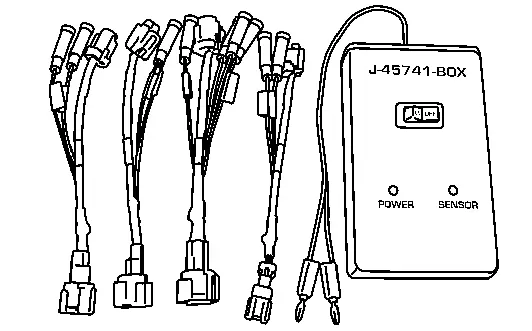 |
Checking operation of ABS active wheel sensor |
— (NI-46534) Trim Tool Set |
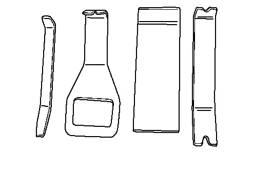 |
Removing trim components |
Commercial Service Tools
| Tool name | Description | |
1. Flare nut crowfoot 2. Torque wrench |
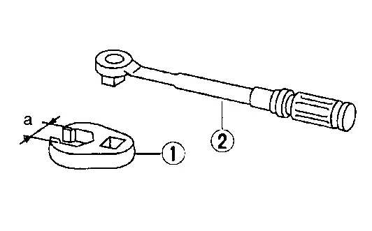 |
Tightening brake tube flare nuts a: 10 mm (0.39 in)/12 mm (0.47 in) |
| Power tool | 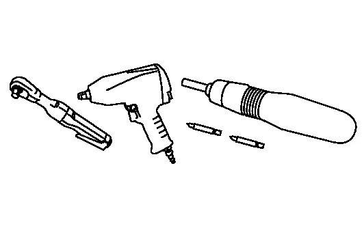 |
Loosening nuts, screws and bolts |
Ecu Diagnosis Information. Abs Actuator and Electric Unit (control Unit) Nissan Pathfinder
Reference Value
VALUES ON THE DIAGNOSIS TOOL
| Item | Condition | Reference valve in normal operation |
|---|---|---|
| Steering angle | When driving straight | ±2.5° deg |
| When steering wheel is steered to RH by 90° | Approx. +90° deg | |
| When steering wheel is steered to LH by 90° | Approx. -90° deg | |
| Battery voltage | Ignition switch ON | 10 – 16 V |
| FR LH wheel speed | Nissan Pathfinder Vehicle stopped | 0.00 MPH (km/h) |
| When driving*1 | Nearly matches the speedometer display (within ±10%) |
|
| FR RH wheel speed | Nissan Pathfinder Vehicle stopped | 0 mph (km/h) |
| When driving*1 | Nearly matches the speedometer display (within ±10%) |
|
| RR LH wheel speed | Nissan Pathfinder Vehicle stopped | 0 mph (km/h) |
| When driving*1 | Nearly matches the speedometer display (within ±10%) |
|
| RR RH wheel speed | Nissan Pathfinder Vehicle stopped | 0 mph (km/h) |
| When driving*1 | Nearly matches the speedometer display (within ±10%) |
|
| Nissan Pathfinder Vehicle speed | Vehicle stopped | 0 mph (km/h) |
| When driving*1 | Nearly matches the speedometer display (within ±10%) |
|
| Odometer | Always | Nearly matches the odometer display |
| Decel G sensor | When stopped | Approx. 0 m/s2 |
| During acceleration | Positive value | |
| During deceleration | Negative value | |
| Side G sensor | Nissan Pathfinder Vehicle stopped | Approx. 0 G |
| Right turn | Negative value | |
| Left turn | Positive value | |
| Yaw rate sensor | Nissan Pathfinder Vehicle stopped | Approx. 0 deg/s |
| Turning right | Negative value | |
| Turning left | Positive value | |
| Master cylinder pressure | Brake pedal not depressed | Approx. 0 bar |
| Brake pedal depressed | (−40) – 300 bar (Pressure increases according to pedal effort) |
|
| Valve, pump motor | Active | On |
| Inactive | Off | |
| FL/RR valve | Active | On |
| Inactive | Off | |
| FR/RL valve | Active | On |
| Inactive | Off | |
| FL/RR pump | Active | On |
| Inactive | Off | |
| FR/RL pump | Active | On |
| Inactive | Off | |
| RR RH ABS OUT valve*2 | Active | On |
| Inactive | Off | |
| RR RH AND IN valve*2 | Active | On |
| Inactive | Off | |
| RR LH ABS OUT valve*2 | Active | On |
| Inactive | Off | |
| RR LH ABS IN valve*2 | Active | On |
| Inactive | Off | |
| FR RH ABS OUT valve*2 | Active | On |
| Inactive | Off | |
| FR RH ABS IN valve*2 | Active | On |
| Inactive | Off | |
| FR LH ABS OUT valve*2 | Active | On |
| Inactive | Off | |
| FR LH ABS IN valve*2 | Active | On |
| Inactive | Off | |
| Front tire diameter | Always | Tire diameter (mm) |
| Transmission type | M/T models | M/T |
| A/T models | A/T | |
| CVT models | CVT | |
| DCT models | DCT | |
| Type is not configuration | Not | |
| Parking brake type | Manual parking models | 1 |
| Electric parking brake models (Cable type) | 2 | |
| Electric parking brake models (drum brake type) | 3 | |
| Electric parking brake models (disc brake type) | 4 | |
| Type is not configuration | 5 | |
| Stop lamp | Stop lamp is turned ON | On |
| Stop lamp is turned OFF | Off | |
| AEB/IEB max torque 4 | When moderate mode | Depends on the Nissan Pathfinder vehicle status |
| AEB/IEB max torque 3 | When strong mode | Depends on the Nissan Pathfinder vehicle status |
| AEB/IEB max torque 2 | When city mode | Depends on the Nissan Pathfinder vehicle status |
| AEB/IEB max torque 1 | When pedestrian mode | Depends on the Nissan Pathfinder vehicle status |
| Electric parking mode | Customer mode | Mode 1 |
| Factory mode | Mode 2 | |
| ACTUATOR VOLT (RH) | Ignition switch ON | 10 - 16 V |
| ACTUATOR VOLT (LH) | Ignition switch ON | 10 - 16 V |
| ACTUATOR CURRENT (RH) | Active | 16 - 27 A |
| Inactive | Approx. 0 A | |
| ACTUATOR CURRENT (LH) | Active | 16 - 27 A |
| Inactive | Approx. 0 A | |
| SLOPE RATIO | When on a level road | 0 % |
| When on a sloping road | (–90) % − 90 % | |
| BR FORCE EST (RH) | Active | 0 KN |
| Inactive | 9 − 25.0 kN | |
| BR FORCE EST (LH) | Active | 0 KN |
| Inactive | 9 − 25.0 kN | |
| PB SW | Parking brake switch is pulled | PULL |
| Parking brake switch is not operated | N | |
| Parking brake switch is pushed | PUSH | |
| Parking brake switch is malfunctioning | MALF | |
| MALF LEVEL | Normal | NORMAL |
| Malfunctioning (part replacement required) | REPAIR | |
| Malfunctioning (function stopped) | STOP | |
| BRAKE STATUS (LH) | Apply (start) | ACT 1 |
| Apply (during) | ACT 2 | |
| Apply (end) | ACT 3 | |
| Release (start) | RLS 1 | |
| Release (during) | RLS 2 | |
| Release (end) | RLS 3 | |
| When replacing brake pad | RLS 4 | |
| Unknon | UNKNO | |
| Initialize | INT | |
| BRAKE STATUS (RH) | Apply (start) |
ACT 1 |
| Apply (durnig) | ACT 2 | |
| Apply (end) | ACT 3 | |
| Release (start) | RLS 1 | |
| Release (during) | RLS 2 | |
| Release (end) | RLS 3 | |
| When replacing brake pad | RLS 4 | |
| Unknon | UNKNO | |
| Initialize | INT | |
| BR DISC TEMP 1 | Always | Changes according to (current) temperature of disc rotor |
| BR DISC TEMP 2 | Displayed but not used | — |
| PB ACTIVE STATUS DISP | Release | REL |
| Apply (when the parking brake switch is pulled once) | ACT 1 | |
| Apply (when the parking brake switch is pulled twice ore more) | ACT 2 | |
| Not confirmed | UNCON | |
| PB MALF DISP | Normal | NORMAL |
| Malfunction | MALF 1 | |
| Displays but not used | MALF 2 | |
| Nissan Pathfinder Vehicle STATUS | No warning | NOT |
| Nissan Pathfinder Vehicle is move backward | WARN | |
| EPB warning 1 | No warning | Off |
| When the driver gets out of the Nissan Pathfinder vehicle without activating electric parking brake system. | Warning | |
| PB WARNING 1 | No warning | NO |
| When the condition that the electric parking brake system is turned ON under the condition that it is unable to be activated. (Displays the “Press brake pedal” by information display in the combination meter) | WARN 1 | |
| When the condition that the electric parking brake system is turned ON again under the condition that it is unable to be activated.(Displays the “Press brake pedal” by information display in the combination meter) | WARN 2 | |
| PB WARNING 2 | No warning | NO |
| When the parking brake switch is pressed without depressing the brake pedal. (Displays the “Press brake pedal” by information display in the combination meter) | WARN 1 | |
| When the parking brake switch is pressed again without depressing the brake pedal. (Displays the “Press brake pedal” by information display in the combination meter) | WARN 2 | |
| PB WARNING 3 | No warning | NO |
| When the parking brake switch is continued to be pulled while the Nissan Pathfinder vehicle is travelling. (Displays the “Release parking brake” by information display in the combination meter, master warning lamp turns ON and buzzer is operate) | WARN | |
| PB WARNING 4 | No warning | NO |
| When the electric parking brake system cannot be cancelled automatically after trying this without fastening the seat belt. (Displays the “Release parking brake” by information display in the combination meter) | WARN 1 | |
| When the electric parking brake system cannot be cancelled automatically after trying this again without fastening the seat belt. (Displays the “Release parking brake” by information display in the combination meter) | WARN 2 | |
| PB SW indicator*3 | Parking switch indicator lamp is ON | On |
| Parking switch indicator lamp is blinking | Blink | |
| Parking switch indicator lamp is OFF | Off | |
| EPB warning 2 | When electric parking brake system is normal. | Not |
| When the malfunctioning of electric parking brake system is detected. | Warn 1 | |
| When the critical malfunctioning of electric parking brake system is being detected. | Warn 2 | |
| When the malfunctioning of electric parking brake signal is detected. | Warn 3 |
*1: Confirm tire pressure is standard value.
*2: Display occasionally changes On/Off for a moment after ignition switch is placed ON. This is operation for checking purposes and is not a malfunction.
*3: Refer to System Description for ON/OFF/BRINK conditions of each warning lamp and each indicator lamp, buzzer and information display in the combination meter.
Fail-Safe
VDC FUNCTION, TCS FUNCTION, ACTIVE BRAKE LIMITED SLIP (ABLS) FUNCTION, BRAKE ASSIST FUNCTION, BRAKE FORCE DISTRIBUTION FUNCTION, hill start assist FUNCTION
VDC warning lamp in combination meter turn ON when a malfunction occurs in system [ABS actuator and electric unit (control unit)]. The control is suspended for VDC function, TCS function, active brake limited slip (ABLS) function, brake assist function, brake force distribution function, and hill start assist function. The Nissan Pathfinder vehicle status becomes the same as models without VDC function, TCS function, active brake limited slip (ABLS) function, brake assist function, brake force distribution function, and hill start assist function. However, ABS function and EBD function are operated normally.
ABS FUNCTION
ABS warning lamp and VDC warning lamp in combination meter turn ON when a malfunction occurs in system [ABS actuator and electric unit (control unit)]. The control is suspended for VDC function, TCS function, ABS function, active brake limited slip (ABLS) function, brake assist function, brake force distribution function, and hill start assist function. The Nissan Pathfinder vehicle status becomes the same as models without VDC function, TCS function, ABS function, active brake limited slip (ABLS) function, brake assist function, brake force distribution function, and hill start assist function. However, EBD function is operated normally.
EBD FUNCTION
ABS warning lamp, brake warning lamp and VDC warning lamp in combination meter turn ON when a malfunction occurs in system [ABS actuator and electric unit (control unit)]. The control is suspended for VDC function, TCS function, ABS function, EBD function, active brake limited slip (ABLS) function, brake assist function, brake force distribution function, and hill start assist function. The Nissan Pathfinder vehicle status becomes the same as models without VDC function, TCS function, ABS function, EBD function, active brake limited slip (ABLS) function, brake assist function, brake force distribution function, and hill start assist function.
ELECTRIC PARKING BRAKE FUNCTION
The electric parking brake warning lamp and/or electric parking indicator lamp turns ON when a malfunction with the system occurs.
When parking brake switch is pulled/pushed during system malfunction, electric parking brake indicator lamp blinks and electric parking brake warning lamp turns ON when electric parking brake cannot be operated. It restricts braking and release operations of electric parking brake.
| DTC | Fail-safe condition |
|---|---|
| C1040-63 | Normal control |
| C1040-64 | |
| C1040-92 | |
| C1041-55 | |
| C1042-04 | The following functions are suspended:
|
| C1043-04 | |
| C1046-04 | |
| C1047-04 | |
| C1048-04 | |
| C1048-11 | |
| C1048-92 | |
| C1049-04 | |
| C104A-04 | |
| C104B-04 | |
| C104C-04 | |
| C104D-04 | |
| C104E-04 | |
| C104F-04 | |
| C1050-04 | |
| C1051-04 | |
| C1051-13 | |
| C1051-1C | |
| C1056-13 | Normal control |
| C1056-16 | The following functions are suspended:
|
| C1056-17 | |
| C1058-04 | |
| C1058-42 | |
| C1058-44 | |
| C1058-49 | |
| C1058-51 | |
| C1058-92 | |
| C105A-92 | |
| C105D-7B | The following functions are suspended:
|
| C105F-85 | Normal control |
| C105F-92 | |
| C1061-02 | The following functions are suspended:
|
| C1061-07 | |
| C1061-09 | |
| C1061-11 | |
| C1061-12 | |
| C1061-13 | |
| C1061-1C | |
| C1061-38 | |
| C1061-4A | |
| C1061-64 | |
| C1063-02 | |
| C1063-07 | |
| C1063-09 | |
| C1063-11 | |
| C1063-12 | |
| C1063-13 | |
| C1063-1C | |
| C1063-38 | |
| C1063-4A | |
| C1063-64 | |
| C1065-02 | |
| C1065-07 | |
| C1065-09 | |
| C1065-11 | |
| C1065-12 | |
| C1065-13 | |
| C1065-1C | |
| C1065-38 | |
| C1065-4A | |
| C1065-64 | |
| C1067-02 | |
| C1067-07 | |
| C1067-09 | |
| C1067-11 | |
| C1067-12 | |
| C1067-12 | |
| C1067-13 | |
| C1067-1C | |
| C1067-38 | |
| C1067-4A | |
| C1067-64 | |
| C1068-95 | |
| C1069-95 | |
| C106A-04 | |
| C106A-55 | |
| C106A-62 | |
| C106A-64 | |
| C106B-64 | The following functions are suspended:
|
| C106C-01 | |
| C106C-02 | |
| C106C-16 | |
| C106C-17 | |
| C106D-01 | |
| C106E-54 | |
| C106E-55 | |
| C106E-64 | |
| C106F-54 | |
| C1070-01 | |
| C1070-54 | |
| C1070-64 | |
| C1071-54 | |
| C1071-61 | |
| C1071-64 | |
| C1072-01 | |
| C1072-64 | |
| C1072-83 | |
| C1073-01 | The following functions are suspended:
|
| C1073-1C | |
| C1073-55 | The following functions are suspended:
|
| C1073-64 | The following functions are suspended:
|
| C1076-55 | The following functions are suspended:
|
| C1077-55 | Normal control |
| C1077-92 | |
| C1078-55 | |
| C1079-55 | |
| C107A-55 | |
| C107B-53 | |
| C107C-53 | |
| C1080-86 | The following functions are suspended:
|
| C1082-86 | |
| C1083-86 | |
| C1085-86 | |
| C1086-86 | The following functions are suspended:
|
| C1087-86 | The following functions are suspended.
|
| C1088-86 | Normal control |
| C1090-86 | |
| C1092-86 | |
| C1096-86 | |
| C10AA-63 | |
| C10AC-54 | The following functions are suspended:
|
| C10AF-01 | Normal control |
| C10B0-01 | The following functions are suspended:
|
| C10B0-09 | |
| C10B1-01 | |
| C10B1-09 | |
| C10B2-01 | |
| C10B2-64 | |
| C10B3-44 | |
| C10B3-49 | |
| C10B3-53 | |
| C10B3-55 | |
| C10B3-68 | |
| C10B4-98 | |
| C10B5-76 | |
| C10B6-68 | |
| C10B7-16 | |
| C10B8-77 | |
| C10B9-77 | |
| U0076-00 | The following functions are suspended:
|
| U0076-88 | |
| U2140-87 | |
| U214E-87 | |
| U214F-87 | |
| U2152-87 | Normal control |
| U2156-87 | The following functions are suspended:
|
| U2240-87 | |
| U2241-87 | |
| U224A-87 | Normal control |
| U224E-87 | |
| U2252-87 | |
| U225B-87 | The following functions are suspended:
|
| U2276-87 |
DTC Inspection Priority Chart
When multiple DTCs are displayed simultaneously, check one by one depending on the following priority list.
U0076-00 Control module comm Bus D Off
U0076-88 Control module comm Bus D Off
C1082-86 CAN comm err (TCM)
C1086-86 CAN comm err (BCM)
U2140-87 CAN comm err (ECM)
U214E-87 CAN comm err (combination meter)
U214F-87 CAN comm err (BCM)
U2152-87 CAN comm err (ADAS control unit)
U2156-87 CAN comm err (steering angel sensor)
U2240-87 CAN comm err (ECM)
U2241-87 CAN comm err (TCM)
U224A-87 CAN comm err (AWD/4WD)
U224E-87 CAN comm err (combination meter)
U2252-87 CAN comm err (ADAS control unit)
U225B-87 CAN comm err (IPDM E/R)
U2276-87 CAN comm err (CCM/ST angle sensor)
C1041-55 Configuration
C1058-04 Control unit
C1058-42 Control unit
C1058-44 Control unit
C1058-49 Control unit
C1058-51 Control unit
C1058-92 Control unit
C105A-92 Control unit
C105F-85 Control unit
C105F-92 Control unit
C1076-55 Not configured
C1078-55 Not configuration
C1079-55 Not configuration
C107A-55 Not configuration
C107B-53 VDC function
C107C-53 Not configuration
C10B3-49 Parking brake control module
C10B3-53 Parking brake control module
C10B3-55 Parking brake control module
C10B3-68 Parking brake control module
C10B5-76 Parking brake assembly check
C10B6-68 Parking brake system
C10B8-77 Parking brake system
C10B9-77 Parking brake system
C1040-63 Emergency brake
C1040-64 Emergency brake
C1040-92 Emergency brake
C106B-64 Stop lamp SW
C106E-54 Steering angle sensor
C106E-55 Steering angle sensor
C106E-64 Steering angle sensor
C106F-54 Steering angle sensor
C1077-55 DDS switch
C1077-92 DDS switch
C1080-86 ECM
C1083-86 Steering angle sensor
C1085-86 Combination meter
C1087-86 IPDM E/R
C1088-86 AV system
C1090-86 ADAS control unit
C1092-86 4WD invalid data
C1096-86 Chassis control module
C1048-04 Valve relay
C1048-11 Valve relay
C1048-92 Valve relay
C1051-04 Pump motor
C1051-13 Pump motor
C1051-1C Pump motor
C1056-13 Battery power supply
C1056-16 Battery power supply
C1056-17 Battery power supply
C10AA-63 Pump motor
C10B0-09 Parking brake actuator (RH)
C10B1-09 Parking brake actuator (LH)
C10B7-16 Parking brake power supply
C1042-04 Cut valve 1
C1043-04 Cut valve 2
C1046-04 Suction valve 1
C1047-04 Suction valve 2
C1049-04 FR LH ABS IN valve
C104A-04 FR LH ABS OUT valve
C104B-04 FR RH ABS IN valve
C104C-04 FR RH ABS OUT valve
C104D-04 RR LH ABS IN valve
C104E-04 RR LH ABS OUT valve
C104F-04 RR RH ABS IN valve
C1050-04 RR RH ABS OUT valve
C106C-01 Pressure sensor
C106C-02 Pressure sensor
C106C-16 Pressure sensor
C106C-17 Pressure sensor
C1070-01 Side G sensor
C1070-54 Side G sensor
C1070-64 Side G sensor
C1071-54 Decel G sensor
C1071-61 Decel G sensor
C1071-64 Decel G sensor
C1072-01 Yaw rate sensor
C1072-64 Yaw rate sensor
C1072-83 Yaw rate sensor
C10AC-54 Calibration incomplete
C10AF-01 Pressure sensor
C10B4-98 Overheat
C1061-02 FR LH wheel sensor
C1061-07 FR LH wheel sensor
C1061-09 FR LH wheel sensor
C1061-11 FR LH wheel sensor
C1061-12 FR LH wheel sensor
C1061-13 FR LH wheel sensor
C1061-1C FR LH wheel sensor
C1061-38 FR LH wheel sensor
C1061-4A FR LH wheel sensor
C1061-64 Wheel sensor FL
C1063-02 FR RH wheel sensor
C1063-07 FR RH wheel sensor
C1063-09 FR RH wheel sensor
C1063-11 FR RH wheel sensor
C1063-12 FR RH wheel sensor
C1063-13 FR RH wheel sensor
C1063-1C FR RH wheel sensor
C1063-38 FR RH wheel sensor
C1063-4A FR RH wheel sensor
C1063-64 Wheel sensor FRr
C1065-02 RR LH wheel sensor
C1065-07 RR LH wheel sensor
C1065-09 RR LH wheel sensor
C1065-11 RR LH wheel sensor
C1065-12 RR LH wheel sensor
C1065-13 RR LH wheel sensor
C1065-1C RR LH wheel sensor
C1065-38 RR LH wheel sensor
C1065-4A RR LH wheel sensor
C1065-64 Wheel sensor RL
C1067-02 RR RH wheel sensor
C1067-07 RR RH wheel sensor
C1067-09 RR RH wheel sensor
C1067-11 RR RH wheel sensor
C1067-12 RR RH wheel sensor
C1067-13 RR RH wheel sensor
C1067-1C RR RH wheel sensor
C1067-38 RR RH wheel sensor
C1067-4A RR RH wheel sensor
C1067-64 Wheel sensor RR
C1068-95 Front wheel sensor
C1069-95 Rear wheel sensor
C106A-04 Wheel sensor
C106A-55 Wheel sensor
C106A-62 Wheel sensor
C106A-64 Wheel sensor
C106D-01 Brake booster
C1073-01 Vacuum sensor
C1073-1C Vacuum sensor
C1073-55 Vacuum sensor
C1073-64 Vacuum sensor
C10B0-01 Parking brake actuator (RH)
C10B1-01 Parking brake actuator (LH)
C10B2-01 Parking brake switch
C10B2-64 Parking brake switch
C10B3-44 Parking brake control module
C105D-7B Brake fluid level low
DTC Index
Self Diagnostic Result
| DTC | Display item | VDC warning lamp | ABS warning lamp | Brake warning lamp | Electric parking brake warning lamp | Refer to |
|---|---|---|---|---|---|---|
| C1040-63 | Emergency brake | DTC Description | ||||
| C1040-64 | ||||||
| C1040-92 | ||||||
| C1041-55 | Configuration | 〇 | DTC Description | |||
| C1042-04 | Cut valve 1 | 〇 | 〇 | 〇 | DTC Description | |
| C1043-04 | Cut valve 2 | 〇 | 〇 | 〇 | DTC Description | |
| C1046-04 | Suction valve 1 | 〇 | 〇 | 〇 | DTC Description | |
| C1047-04 | Suction valve 2 | 〇 | 〇 | 〇 | DTC Description | |
| C1048-04 | Valve relay | 〇 | 〇 | 〇 | DTC Description | |
| C1048-11 | 〇 | 〇 | 〇 | |||
| C1048-92 | 〇 | 〇 | 〇 | |||
| C1049-04 | FR LH ABS IN valve | 〇 | 〇 | 〇 | DTC Description | |
| C104A-04 | FR LH ABS OUT valve | 〇 | 〇 | 〇 | DTC Description | |
| C104B-04 | FR RH ABS IN valve | 〇 | 〇 | 〇 | DTC Description | |
| C104C-04 | FR RH ABS OUT valve | 〇 | 〇 | 〇 | DTC Description | |
| C104D-04 | RR LH ABS IN valve | 〇 | 〇 | 〇 | DTC Description | |
| C104E-04 | RR LH ABS OUT valve | 〇 | 〇 | 〇 | DTC Description | |
| C104F-04 | RR RH ABS IN valve | 〇 | 〇 | 〇 | DTC Description | |
| C1050-04 | RR RH ABS OUT valve | 〇 | 〇 | 〇 | DTC Description | |
| C1051-04 | Pump motor | 〇 | 〇 | 〇 | DTC Description | |
| C1051-13 | 〇 | 〇 | 〇 | |||
| C1051-1C | 〇 | 〇 | 〇 | |||
| C1056-13 | Battery power supply | DTC Description | ||||
| C1056-16 | 〇 | 〇 | 〇 | 〇 | ||
| C1056-17 | 〇 | 〇 | 〇 | 〇 | ||
| C1058-04 | Control unit | 〇 | 〇 | 〇 | 〇 | DTC Description |
| C1058-42 | 〇 | 〇 | 〇 | 〇 | ||
| C1058-44 | 〇 | 〇 | 〇 | 〇 | ||
| C1058-49 | 〇 | |||||
| C1058-51 | 〇 | 〇 | 〇 | 〇 | ||
| C1058-92 | 〇 | 〇 | 〇 | 〇 | ||
| C105A-92 | Control unit | 〇 | 〇 | 〇 | DTC Description | |
| C105D-7B | Brake fluid level low | 〇 | DTC Description | |||
| C105F-85 | Control unit | DTC Description | ||||
| C105F-92 | ||||||
| C1061-02 | FR LH wheel sensor | 〇 | 〇 | DTC Description | ||
| C1061-07 | 〇 | 〇 | ||||
| C1061-09 | 〇 | 〇 | ||||
| C1061-11 | 〇 | 〇 | ||||
| C1061-12 | 〇 | 〇 | ||||
| C1061-13 | 〇 | 〇 | ||||
| C1061-1C | 〇 | 〇 | 〇 | |||
| C1061-38 | 〇 | 〇 | ||||
| C1061-4A | 〇 | 〇 | ||||
| C1061-64 | 〇 | 〇 | ||||
| C1063-02 | FR RH wheel sensor | 〇 | 〇 | DTC Description | ||
| C1063-07 | 〇 | 〇 | ||||
| C1063-09 | 〇 | 〇 | ||||
| C1063-11 | 〇 | 〇 | ||||
| C1063-12 | 〇 | 〇 | ||||
| C1063-13 | 〇 | 〇 | ||||
| C1063-1C | 〇 | 〇 | 〇 | |||
| C1063-38 | 〇 | 〇 | ||||
| C1063-4A | 〇 | 〇 | ||||
| C1063-64 | 〇 | 〇 | ||||
| C1065-02 | RR LH wheel sensor | 〇 | 〇 | DTC Description | ||
| C1065-07 | 〇 | 〇 | ||||
| C1065-09 | 〇 | 〇 | ||||
| C1065-11 | 〇 | 〇 | ||||
| C1065-12 | 〇 | 〇 | ||||
| C1065-13 | 〇 | 〇 | ||||
| C1065-1C | 〇 | 〇 | 〇 | |||
| C1065-38 | 〇 | 〇 | ||||
| C1065-4A | 〇 | 〇 | ||||
| C1065-64 | Wheel sensor RL | 〇 | 〇 | DTC Description | ||
| C1067-02 | RR RH wheel sensor | 〇 | 〇 | DTC Description | ||
| C1067-07 | 〇 | 〇 | ||||
| C1067-09 | 〇 | 〇 | ||||
| C1067-11 | 〇 | 〇 | ||||
| C1067-12 | 〇 | 〇 | ||||
| C1067-13 | 〇 | 〇 | ||||
| C1067-1C | 〇 | 〇 | ||||
| C1067-38 | 〇 | 〇 | ||||
| C1067-4A | 〇 | 〇 | ||||
| C1067-64 | Wheel sensor RR | 〇 | 〇 | DTC Description | ||
| C1068-95 | Front wheel sensor | 〇 | 〇 | DTC Description | ||
| C1069-95 | Rear wheel sensor | 〇 | 〇 | DTC Description | ||
| C106A-04 | Wheel sensor | 〇 | 〇 | 〇 | 〇 | DTC Description |
| C106A-55 | 〇 | |||||
| C106A-62 | 〇 | 〇 | 〇 | 〇 | ||
| C106A-64 | 〇 | 〇 | 〇 | 〇 | ||
| C106B-64 | Stop lamp SW | 〇 | 〇 | DTC Description | ||
| C106C-01 | Pressure sensor | 〇 | DTC Description | |||
| C106C-02 | 〇 | |||||
| C106C-16 | 〇 | |||||
| C106C-17 | 〇 | |||||
| C106D-01 | Brake booster | DTC Description | ||||
| C106E-54 | Steering angle sensor | 〇 | DTC Description | |||
| C106E-55 | 〇 | |||||
| C106E-64 | 〇 | |||||
| C106F-54 | Steering angle sensor | 〇 | DTC Description | |||
| C1070-01 | Side G sensor | 〇 | DTC Description | |||
| C1070-54 | 〇 | 〇 | ||||
| C1070-64 | 〇 | 〇 | ||||
| C1071-54 | Decel G sensor | 〇 | DTC Description | |||
| C1071-61 | 〇 | 〇 | ||||
| C1071-64 | 〇 | 〇 | ||||
| C1072-01 | Yaw rate sensor | 〇 | DTC Description | |||
| C1072-64 | 〇 | |||||
| C1072-83 | 〇 | |||||
| C1073-01 | Vacuum sensor | 〇 | DTC Description | |||
| C1073-1C | 〇 | |||||
| C1073-55 | 〇 | |||||
| C1073-64 | 〇 | |||||
| C1076-55 | Not configured | 〇 | 〇 | 〇 | DTC Description | |
| C1077-55 | DDS switch | 〇 | DTC Description | |||
| C1077-92 | 〇 | |||||
| C1078-55 | Not configuration | 〇 | DTC Description | |||
| C1079-55 | Not configuration | 〇 | DTC Description | |||
| C107A-55 | Not configuration | 〇 | DTC Description | |||
| C107B-53 | VDC function | DTC Description | ||||
| C107C-53 | Not configuration | DTC Description | ||||
| C1080-86 | ECM | 〇 | 〇 | DTC Description | ||
| C1082-86 | CAN comm err (TCM) | 〇 | DTC Description | |||
| C1083-86 | Steering angle sensor | 〇 | DTC Description | |||
| C1085-86 | Combination meter | 〇 | DTC Description | |||
| C1086-86 | CAN comm err (BCM) | 〇 | 〇 | DTC Description | ||
| C1087-86 | IPDM E/R | DTC Description | ||||
| C1088-86 | AV system | DTC Description | ||||
| C1090-86 | ADAS control unit | DTC Description | ||||
| C1092-86 | 4WD invalid data | DTC Description | ||||
| C1096-86 | Chassis control module | DTC Description | ||||
| C10AA-63 | Pump motor | DTC Description | ||||
| C10AC-54 | Calibration incomplete | 〇 | DTC Description | |||
| C10AF-01 | Pressure sensor | 〇 | DTC Description | |||
| C10B0-01 | Parking brake actuator (RH) | 〇 | DTC Description | |||
| C10B0-09 | 〇 | |||||
| C10B1-01 | Parking brake actuator (LH) | 〇 | DTC Description | |||
| C10B1-09 | 〇 | |||||
| C10B2-01 | Parking brake switch | 〇 | DTC Description | |||
| C10B2-64 | 〇 | |||||
| C10B3-44 | Parking brake control module | 〇 | DTC Description | |||
| C10B3-49 | 〇 | |||||
| C10B3-53 | 〇 | |||||
| C10B3-55 | 〇 | |||||
| C10B3-68 | 〇 | |||||
| C10B4-98 | Overheat | 〇 | DTC Description | |||
| C10B5-76 | Parking brake assembly check | 〇 | DTC Description | |||
| C10B6-68 | Parking brake system | DTC Description | ||||
| C10B7-16 | Parking brake power supply | 〇 | DTC Description | |||
| C10B8-77 | Parking brake system | 〇 | DTC Description | |||
| C10B9-77 | Parking brake system | 〇 | DTC Description |
Network-DTC
| DTC | Display item | VDC warning lamp | ABS warning lamp | Brake warning lamp | Electric parking brake warning lamp | Refer to |
|---|---|---|---|---|---|---|
| U0076-00 | Control module comm Bus D Off | 〇 | DTC Description | |||
| U0076-88 | 〇 | 〇 | ||||
| U2140-87 | CAN comm err (ECM) | DTC Description | ||||
| U214E-87 | CAN comm err (combination meter) | DTC Description | ||||
| U214F-87 | CAN comm err (BCM) | 〇 | 〇 | DTC Description | ||
| U2152-87 | CAN comm err (ADAS control unit) | DTC Description | ||||
| U2156-87 | CAN comm err (steering angel sensor) | DTC Description | ||||
| U2240-87 | CAN comm err (ECM) | 〇 | 〇 | DTC Description | ||
| U2241-87 | CAN comm err (TCM) | 〇 | DTC Description | |||
| U224A-87 | CAN comm err (AWD/4WD) | DTC Description | ||||
| U224E-87 | CAN comm err (combination meter) | DTC Description | ||||
| U2252-87 | CAN comm err (ADAS control unit) | DTC Description | ||||
| U225B-87 | CAN comm err (IPDM E/R) | 〇 | DTC Description | |||
| U2276-87 | CAN comm err (CCM/ST angle sensor) | 〇 | DTC Description |